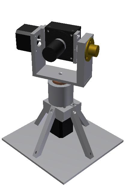
This last semester has kept me busier academically than I’ve ever been before with the main culprits being our two large design projects as well as skripsie. And when i say busy, I mean spending hour after hour through weekends and public holidays in labs working to ensure that projects are complete. The thing is, is that I was having fun. Well to an extent. There were many times where tiredness and frustrations got the better of me, but the moments of joy when something worked were incredible.
The Mechatronics project was interesting, but not my favourite. In theory it was quite simple, but a bit more tricky in application. In essence we were told we needed to take 2 tanks and then have user inputs allowing one to set the desired water level and temperature in both tanks. We were limited by only being able to pump fresh water into tank 1, and only being allowed to place a heating element in tank 1. Our end setup comprised of a kettle as our first tank which we pumped fresh water into. The second tank was placed at a lower height to allow water to flow from the first tank to the second tank. Water could be pumped into tank 1, and then solenoid valves were used to allow water to flow into the second tank, or allow water to flow from either of the tanks back into the reservoir.
 Floats were connected to potentiometers to give us a height/volume reading of the water and supplied thermocouples gave us accurate temperature readings. The entire system is then linked by a Schneider Electric Modicon momentum Soft PLC and Tutorbox. During the term we were given tutorials on how to use Wonderware’s InControl and InTouch software to control the PLC. The project does rather throw one into the deep end though. The training for the PLC doesn’t really explain it’s functionality and very little focus is given on actually programming in the software. Instead we’re taught to make use of RLL programs to control the system.
But the scope of our project was far too complicated to rely on RLL programs. Instead we chose to figure out how to use the other supported Structured Text Language instead. We downloaded some tutorials and beginners guides, but so many of the things we tried gave us compiler errors in the software, so in the end we resorted to a trial and error method, hacking our way through. Till now I’ve only ever really coded in Objected Orientated programming languages, which I don’t really feel STL complies to. This amongst with many other small nuances lead to me hating the programming side of this project. Fortunately one of the group members took to it with vigour.
Our final demo went reasonably well, everything worked to an extent and the “judges” seemed impressed even if the system didn’t run as smoothly as we had hoped.
And onto Digital Design. The basic story is that we were building remote controlled gate units. We had a main board which comprised of a 16 character LCD screen on which we displayed a menu controlled by 5 push buttons. There was a serial->USB converter to communicate with a computer, some EEPROM to store some data a PWM controller to control the “gate” motor, an optical sensor for determining the state of the gate, a triac to turn an AC driven light on/off a buzzer to annoy people and an IR receiver.
We then had a remote with an IR diode for transmitting data, 2 buttons and its own EEPROM for good measure. Both units were based around the Renesas R8/C27 microcontroller programmed in C via Renesas’ HEW software. Fun with that spawned this fan group page. Apart from a few resistor values that had to be calculated, the component design aspect was pretty much handled for us, the big issue was understanding how these components worked, and then getting them to play nice with the rest of the components.
We were given the components every 2nd week or so, and built up our boards slowly as we acquired and programmed each successive piece. In the end we had a board on which each component worked by itself, but then it was time to pull everything together and get the software programmed to work as required. Quite a challenge. This was truly the subject which has taught me the most, or in which I feel I’ve learnt the most. It was work that I hadn’t ever really done, but had always interested me, and although it really is a tough course, and a bit of a trial by fire, I’m glad how it turned out.
As an interesting fact, last year somewhere close to 50% of 4th year Mechatronic Engineers failed the subject. And I can believe that. Although we are given some preparation in the form of a semester of Electronics and 2 semesters of Computer System, the work we do is completely new and requires a different way of thinking and time dedication second to none.
A friend of mine described the subject like this: “Ontwerp n hekmotor en remote. Hier is so 3 bladsye se totally vague instructions, ons sal julle een keer n week kom se presies hoe ver julle agter is. O ja, hier is 6000 bladsye se inligting waardeur jy moet soek vir een pin se default state. Rinse and repeat so 30 miljoen keer. Elke dag”. Roughly translated it is: “Design a gate motor and remote. Here are 3 pages of completely vauge instructions. We’ll come tell you once a week exactly how behind you are. Oh yes, here are 6000 pages of information that you have to search through to find one pins defaults state. Rinse and repeat about 30 million times. Every Day.”
Although a bit dramatic, it quite often feels like. Nothing has frustrated me as much as the unproductive hours spent on this project. We’re busy compiling a report on the project to hand in on Monday, so will post some schematics and pictures then. And then it’s on to exams for 3 weeks, a bit of holiday/skripsie work for 2 weeks, vacation work in East London for 4 weeks and back to Stellenbosch for my last undergrad semester.