Logitech K750 ‘repair’

tl;dr: Thought keyboard was broken, only needed battery replacement.

k750
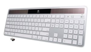
Since the Logitech K750 was first released, I was a fan. But the $100 price tag put me off. It’s most noticeable feature is the fact that it has a bar of solar panels along the top of the board which are used to charge the built in battery. This should mean you never have to replace the battery. A dream come true to me, who in general is disposable battery averse. Besides that it’s a standard wireless keyboard that uses Logitech’s unifying receiver, I additionally like the style and design of the keyboard.

So joyous was I to find it on a half-price special at some stage, promptly ordering it and enjoying it’s use. Two years later, on returning from a short trip, the keyboard no longer worked. Not registering keypresses, nor activating any of it’s notification lights. The battery is not supposed to be replaced, but is relatively easily accessible, so I popped it out and measured the voltage.

ml2032
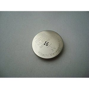
The battery used is a rechargeable coin-cell battery, similar to what is used on motherboards, an ML2032 3.0V battery. My battery measured 2.9V, so I assumed it was still fine, and something else had gone wrong. The keyboard had a 3-year warranty I was still within, so after the retailer rejected me, I contacted Logitech who were kind enough to send me a replacement that continues to work perfectly.

This was over a year ago; in-between a lot has happened, but Logitech didn’t ask me to return the old keyboard, and I couldn’t bring myself to throw it out. I figured I’d salvage the solar panels or something. I found it the other day and decided to take another look. Although the battery comes out relatively easily, the keyboard’s faceplate is glued into place. So to disassemble it you have to pry that off, making reassembly difficult.

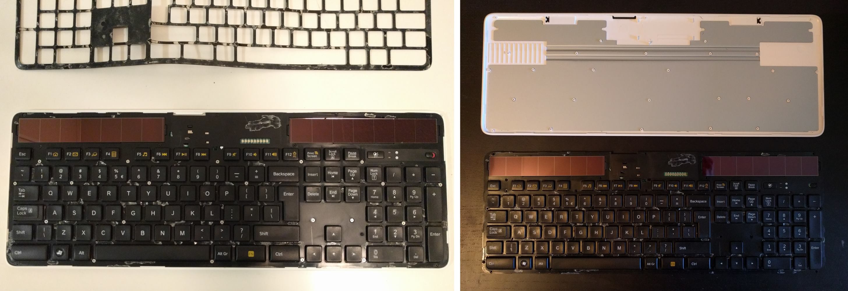
After that there are a number of screws to remove, and then the base separates, giving you access to the circuit-board. On the front are a few test-points. With my old battery plugged in, V_BAT showed 2.86 V and V_MAIN showed a steady 2.0 V. I tested some other components but couldn’t find anything notably wrong with the board. Solar panels provided a charge.

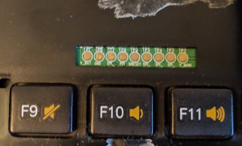
So I popped my battery out of my new keyboard, and lo and behold it worked. I measured the voltage and it reflects marginally over 3.03 V. Apparently a 0.15 V drop on this battery is enough to stop the keyboard working. I measured the V_MAIN on the test points, and it showed an match 2.0V, like with the ‘bad’ battery. This also meant my disassembly was completely unnecessary. So with it in pieces, I ordered a replacement battery.

Now I have two working K750 keyboards, although one is slightly disfigured.

April 2021 Update:
My original keyboard is still working after replacing the battery.
My second only somewhat works. If I try turn it off, it doesn’t turn off immediately, but only after a few minutes. Once it’s off, it can’t be turned back on. However, I’ve found that if ‘jumpstart’ it by shorting the V_BATT and V_MAIN terminals together for a few seconds, then it works again until it is turned off.

Remington F4790 Partial disassembly

Recently the foil on my Remington F4790 got a hole in it, it makes the foil and cutter part of the razor unusable. While I placed replacement foils on order, I figured I’d just use the trimmer, but then trimmer stopped working.

Apologies for the poor image quality, they’re screengrabs from a video.

The foil and the cutters pop straight off with a little bit of a pull. Thereafter there are two small screws at the hinge point which can be loosened.
GP012706.MP4_snapshot_00.01_[2015.10.13_19.56.49]The foil and cutter head then comes out. Take care when reassembling to align the pop-out with the slot on the head.GOPR2706.MP4_snapshot_10.54_[2015.10.13_19.59.41]

From here there are 4 screws easily accessible that can be loosened.

GOPR2706.MP4_snapshot_01.24_[2015.10.13_19.57.57]A black rubber seal is then visible, which comes off easily to reveal two white plastic mechanisms which are driven by a motor. Align the drive shaft (1) on the motor so that the point is away from the trimmer. Plastic mechanism [2] can come straight off. Plastic mechanism [3] drives the trimmer and has a shaft going down. It can now be lifted out.GP012704.MP4_snapshot_00.53_[2015.10.13_20.09.58]There’s a round rubber seal between the trimmer and the motor housing which must be removed. The trimmer must now be fully extended. With a bit of jiggling the trimmer will come out completely. There is a metal spring near the bottom which might catch, see below.GOPR2705.MP4_snapshot_08.02_[2015.10.13_20.04.40]The trimmer is unfortunately a sealed mechanism. The outer casing is two parts which look like they clipped into each other, but looks like some heat was used to ‘seal’ it. Anyway, I pried it apart, because there was nothing left to do. Not too much seemed to break.

GP012704.MP4_snapshot_04.37_[2015.10.13_20.10.55]When I opened it up it was clogged up with hair preventing it from moving. I cleared all of it up, and the cover fortunately managed to clip back together and seemed to hold.GOPR2705.MP4_snapshot_03.06_[2015.10.13_20.02.47]I don’t really know how to disassemble the razor further. There are two screws visible, but loosening them doesn’t achieve anything. Through the clear motor housing other screws can be seen connecting it to the outer case, but no way to access them.

GP012704.MP4_snapshot_00.24_[2015.10.13_20.09.25]

I think the outer case is all just clipped together, but felt nervous in forcing it apart when I still want to use the razor. If my foils don’t make it in the post, then maybe I’ll do it, but for now I can’t see any further way to take the razor apart besides forcing the outer casing apart.

Logitech Z506 demise and disassembly

Back in varsity I had a set of 2.1 channel Logitech speakers. They were great, simple and provided good sound. Alas one day they stopped working, never found out why, even after taking it apart (one had to saw open the wooden sub box) and getting several friends and family members to analyse it. In any case, I ended up purchasing a Logitech Z506 5.1ch set to replace them.

And they’ve done me well. Until recently. I’ve had them for about 3 years; I would have expected a longer life but I fear the recent spate of load shedding (and related grid instability) might have given them a knock (oddly I think it’s what happened to my last set too).

Anyway, they stopped working unexpectedly, so logically I took them apart. You can see the process below. It’s quite nicely put together, but also not with the intent of it being taken apart again later.

In any case I looked around a bit and saw that what I still believe is a fuse was not letting any current through (marked T3.15A250V). So, lacking a replacement fuse, I shorted the fuse and thought I’d fixed the problem, alas I fear there was another reason why the fuse had gone as I plugged the power back in.

Cue loud bang, my lights going out and enough flames to give me a fright. 10 o’clock at night, I made my way to my tripboard and reset the plugs, unfortunately I had also managed to trip the switch in my landlord’s house. Fortunately they were still awake and didn’t ask too many questions as I asked if I could check their tripboard quickly.

So I’m once again in the market for new speakers (edit, managed to revive them, see below), but for others who might have more luck than me, here are instructions to disassemble.

Unscrew the 10 screws on the backpanel. Unscrew the 4 screws mounting the speaker to the bottom of the box. Pull the speaker out. You will notice bendy wire clips stapled to the case holding cables in place, loosen these as required.

Undo screws on back and bottom of speaker

Undo screws on back and bottom of speaker

If you have small hands you can unplug the speaker, but otherwise rest it on top. The backpanel slides out, but there is a bit of double-sided tape holding it in place at the back under the panel. You can release this by pulling the PC-Board away from the side of the box. You can then pull the backpanel and PCB out. This will let you unplug the two plugs on the power supply.

Plugs to unscrew and mounting points

Plugs to unscrew and mounting points

With the main board out, you can loosen the two screws holding the PSU in place and slide it out.

partsSimple as that, above you can see where the fuse I shorted was, and also a bit of the transformer which I think I burnt out. Oops :(

Update:
A bit of searching led me to believe that I could fit a replacement power supply and all would be alright. I had a spare laptop power supply (90W, 19V) lying around, and I wired this up. So far it has been running like that for several months.

It is also possible to buy direct replacement boards, for example here.

Install Flash Drive in A110

The standard 8GB SSD that comes standard in the Acer Aspire is a bit crappy. It’s rather slow, and obviously 8GB isn’t particularly much space. I knew of others who had installed Flash Drives in their netbooks and figured I’d do the same. I couldn’t find any posts about people who had done it, but I did find Tnkgrl who had added a USB bluetooth device to hers and a guy over at WRP & CW – Radio Shack who added a USB fingerprint scanner to his.

They both used different places on the motherboard to access extra USB ports. Both of them work without disabling any of the other USB ports. Tnkrgrl made use of some pins under where the Wi-Fi card is situated, and the Radio Shack hack some points near the CPU. I wasn’t too keen to fiddle with a soldering iron near the CPU, so instead chose to use Tnkgrl’s post for reference. I managed to solder the power wires in quite easily but really battled to get the data wires in place. My soldering iron is unfortunately not built for finicky work like this, so I eventually gave up and decided to use the data points that Radio Shack used.

I purchased a 16GB Kingston Data Traveller G2, stripped it of it’s casing and soldered the appropriate wires to it. Putting everything back together and booting up in Linux revealed the drive to be in working order.

What I plan to do now is to install Windows XP onto the SSD and Linux onto the Flash Drive. Although I am getting very used to Linux, I still have several Apps that I just can’t get to work in Linux, and can find no alternatives.

Below I show how to take apart the Acer. When I did it I followed this guide by Tony Smith.

First remove the battery and unscrew the 6 screws on the underside of the netbook. I have circled them in the following picture. You also need to remove the two rubber feet near where the battery goes, and remove two screws from underneath them.img_4192Turn over the netbook and lift open the screen. The keyboard is held in place by 3 spring loaded clips along the top of the keyboard. I have circled them in the next picture. Using a flat head screw driver or credit card push these in one by one. As each one is pushed in, the top of the keyboard should lift slightly. Once all three of the clips have been pushed in, raise the top of the keyboard slightly and pull it towards the screen. This should allow the hooks at the bottom of the keyboard to come loose. Underneath, the keyboards wires go to the motherboard. It is fairly simple to release the catch on the cables clip on the motherboard, and free it form the netbook.img_4196Next you have to remove 6 screws that hold the casing together, they have been circled in the following picture. You also need to unclip and release the cable that goes from the touchpad to the motherboard.

Next part isn’t that nice. The top part of the casing clips into the bottom half with a series of clips around the edge. You need to stick your screwdriver or credit card in on one end and slowly work your way around the edge of the netbook unclipping it. Once they’re all unclipped you unhook the top parts from just below the screen hinges. You should now have the motherboard in full view.img_4200If you wish to remove the motherboard you must undo the two screws in the lower part of the image above. This will allow you to first remove the wifi card. You must also undo the clip that holds the SSD’s cable in place on the motherboard, and also unplug the pug that carries the wires to the screen in the top right of the screen. To make life easier you should also undo the two screws that keep a hook in place in the top left. This acts as part of the hinge mechanism and to hold the motherboard in place. Underneath the motherboard is another wire harness which carries wires to the board on the right of the laptop.

If you wish to install more/new RAM, this is quite easy, you need simply plug it in to the open slot on the underside of the motherboard.img_4201In this image you can just see where my two data wires solder onto the motherboard by the CPU. At the place there are two columns of solder points. The left column has 4 pins and the right column 5. On the left column the first point (ie the top point) is the Ground, the second point Data+, third point Data-, and fourth (bottom) point 5V+. In my picture I only used the data points.This image from the aforementioned Radio Shack shows the points better. This image from Tnkgrl shows the two power points I used for my Flash Drive, and also the other two Data points that can be used.

For the four points on the Flash Drive itself. Lying the flash drive down with the contacts on top, and to the right. In order from top to bottom, the contacts are: 5V+, Data-, Data+, Ground. I just stashed the flash drive to the right there,forwards of the SSD where there was some space. Because these are just standard USB ports they can be used to install any standard USB device. The guy at Radio Shack actually installed a tiny USB Hub into it, allow new additions to be installed relatively easily.