I have not avoided KiCad in any way, I just don’t use ECAD software much, and when I do, it’s largely for work where we have always used Altium. This year we got some work done by a contract firm. They mentioned they could use Altium, but it was their preference to use KiCad instead. We said that was fine. And all was good in the world.
Several months later and we want to produce something they’ve designed. They provide us all the KiCad files as well as manufacturing outputs, but for us to release this internally, we need to have it formatted in a specific way to match our QMS expected templates. This should be easy though, just apply a template and we’re good. KiCad has a Drawing Sheet Editor which lets you create worksheets, and apply them to your schematics and boards, that sounds like what we need.
And that is true. For schematics, I was able to create a template exactly matching our Altium one, and easily generate documents matching our existing documents. PCBAs on the other hand was a whole different ball game. This ‘issue’ is largely self-inflicted. Our release documentation requires a lot of things to be present in a 3-page PDF that aren’t necessarily that important. Mainly because it’s just duplicating data that is already contained in the Gerbers and other manufacturing output. This is just placed in a PDF that makes it easy for a human to get a quick overview of the design. It has its place.
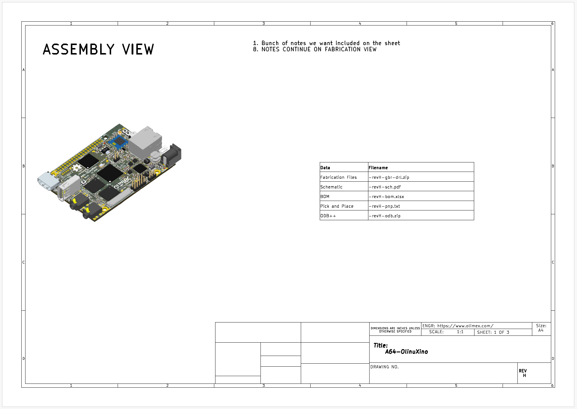
Example output of a generated PDF sheet that includes a 3D image generated by the KiCad CLI (details)
Included in this document are: a 3d-isometric view of the board; a PCB stack-up table; drill map; and a single page with all the layers shown. And Altium’s templates makes this trivial to generate for new designs. KiCad does not. And that’s not KiCad’s fault, it shouldn’t set out to just replicate everything Altium does. These aren’t things that are needed in an ECAD software, it’s just, we had it, and now we don’t.
So what can we do? We can apply a worksheet template to the PCB editor. But it can only really output each layer on a separate page. It’s a start. We can also have custom layers, and put whatever we want on those custom layers, which can be output to separate pages. What can’t we do? Mainly, the Drawing Sheet Editor (as far as I could tell) doesn’t let you template these additional layers’ contents. It can’t generate 3d images of the board, it can’t automatically populate a drill map or board stack-up table. KiCad does support most of these things, just not in an automated template kind of way, so if I wanted to to do this for every new design we release, it’s a lot of time consuming, error-prone work, to get the desired output.
What KiCad does have though is a newly revamped API, as well as several CLI options. And what can we do with these? Well, we can get a long way to matching our Altium implementation.
We can take 3 new layers, and pretend each of them is the desired output page we want. We can use the CLI to do things like generate drill maps and 3D views of the board. We can apply template sheets to the project, and we can generate the final files. We can then use the API to add the elements to our 3 layers; get information from the board and automatically generate table outputs. And then we can piece this together with a PDF editor library. Do we get exactly the same output as with Altium? No, but we get pretty close, and it has everything we need.
You can see a semi-stripped down version of this on GitHub.
There are many aspects of IOT/connected devices that appeal to me. I like looking at data, it’s interesting. I like automation, it can be fun, and convenient. Unfortunately there are many aspects of the current IOT landscape that are extremely unappealing. Universally, not just to me. The obvious solution then is to build my own :)
And that’s what I’ve started doing. Over the past five years, little by little, as I’ve wanted to do something, I’ve put something together, based on what I’ve got lying around. Originally I was making use of a web-based server to store and gather all my data, but got annoyed each time the internet cut off. In hindsight it’s not clear to me why I was experiencing so many connectivity issues at the time that I decided the best option was to host something locally, but that’s where we are today.
Server
The server is a Raspberry Pi. One that I had lying around, and I already had submitting temperature and air pressure data to my server. The server was just a shared hosting site with a few basic php commands to link up with a sql database. To provide some flexility, allow for some customization and make up for my large lack of web-dev experience, I chose to do it all in python. I’m using the CherryPy library to present a basic html web-interface that gives me a summary of what’s going on, and also handles all the data requests coming in from various local sources. If the internet goes down, it doesn’t matter, because everything is stored and presented on the local network.
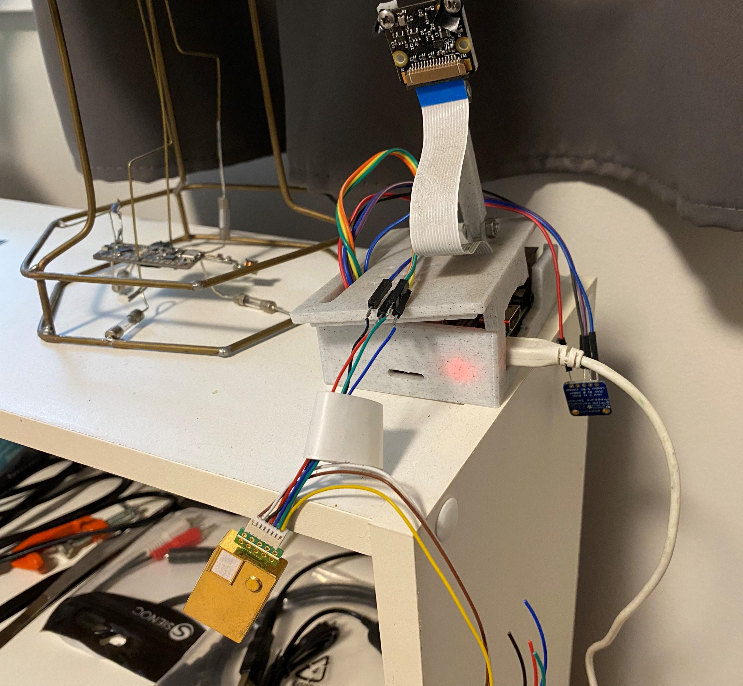
Every time I look at this jumble of wires I tell myself that I should really tidy it up. But it’s working. And then I’d have to take it offline, and the risk of a short isn’t thaaat high. So what would I really get out of the exercise?
At times, like when I’m away from home and need to monitor some things, I can open another port and make it accessible from the internet, but this is off by default, mainly as a security improving effort.
What does it do?
As I worked on integrating the few sensors I had, I realised that this platform I was creating could do more than just save some data and show it to me. Well, more than just weather data. The platform running python made it easy to script all kinds of integrations. As I created more of these, I saw the value in having a standard task based framework on which to build all these integrations.
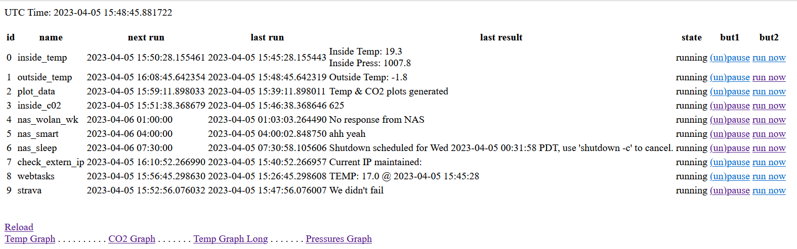
This basis of this is a config file which is read at startup, that reads what tasks need to be load and when they must run. After that, there’s nothing left to do. All the tasks run as scheduled, doing as they must. The main web-interface shows a status for each task, when it was last run, when its next scheduled run is as well as options to start and stop tasks or run them immediately.
Screenshot of the web-interface. Some very useful statuses in there
This scheduler approach is simple. It makes it easy to expand, and it all running on python means it’s easy for me to think of something I want done and implement it, as well as feed back all the results to the ‘server’ directly.
Connected items
So what all is included in my setup?
Raspberry Pi
The Raspberry Pi itself has a BMP180 and an MH-Z19 directly connected to it that it polls occasionally for the latest temperature, air pressure and CO2 levels in my office.
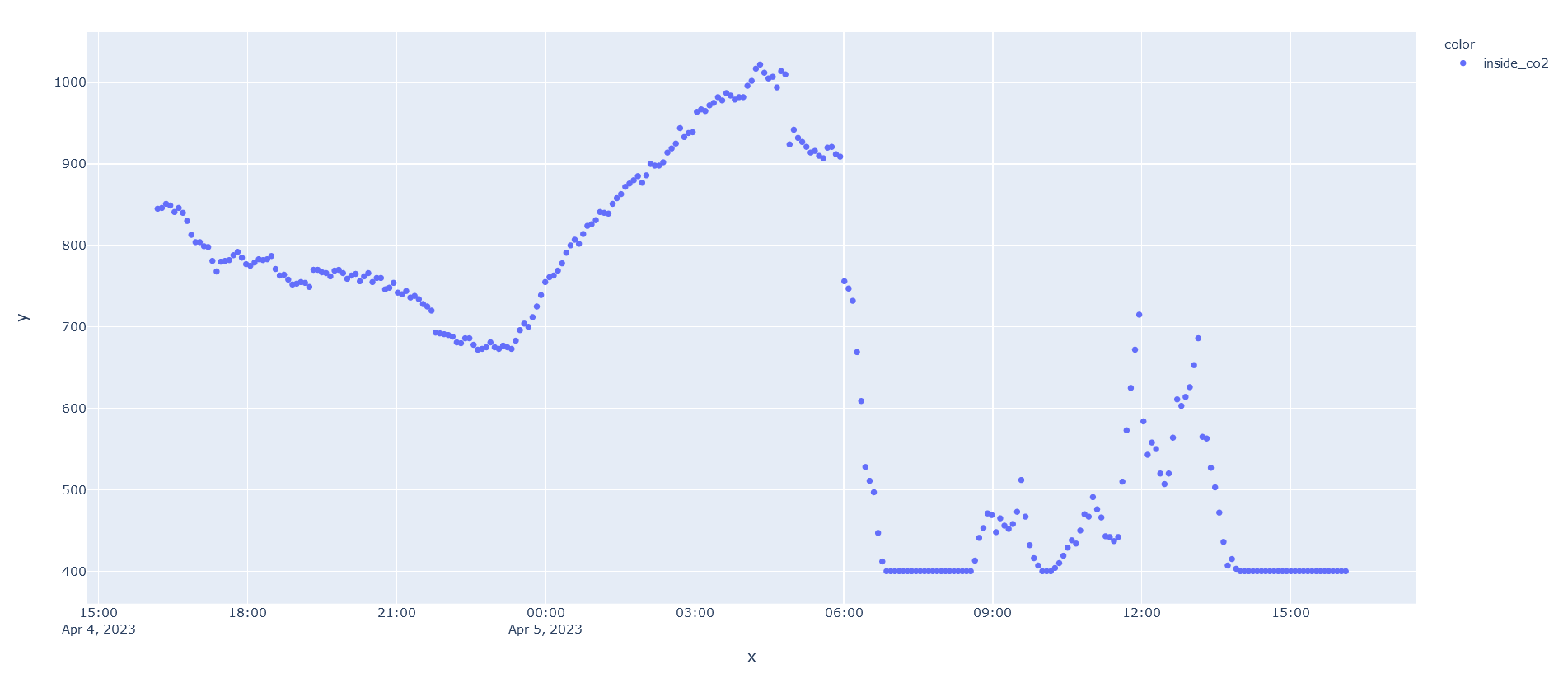
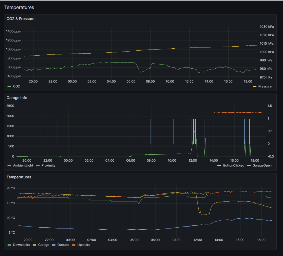
The CO2 sensor was pretty cheap, and accuracy isn’t amazing, along with its ‘auto-calibration’. But it still gives interesting results. It’s especially easy to see build-up in my office when the door is closed, as well as the drop every time the heating runs in the winter, bringing fresh air in. It’s certainly more accurate than this.
CO2 data. Big dip is when the furnace started up after ~12 hrs of not running on a cold (windows closed) but sunny day. Smaller spikes during day are from me closing my office door during a meetingAnd some temperature data to go with it. I think the green spike was some sun shining on the sensor
ESP32
I ‘attended’ one of the Hackaday Remoticon sessions a couple years ago, where someone from DigiKey was presenting on an IOT platform (Machinechat) that they were selling. It did a lot of what I wanted, but the free tier was pretty limited, and why would I pay for something when I can do it myself for free ;) But I had the microcontroller and temperature sensor leftover, so just repurposed it to connect to my own server and feed temperatures from our downstairs.
ESP32
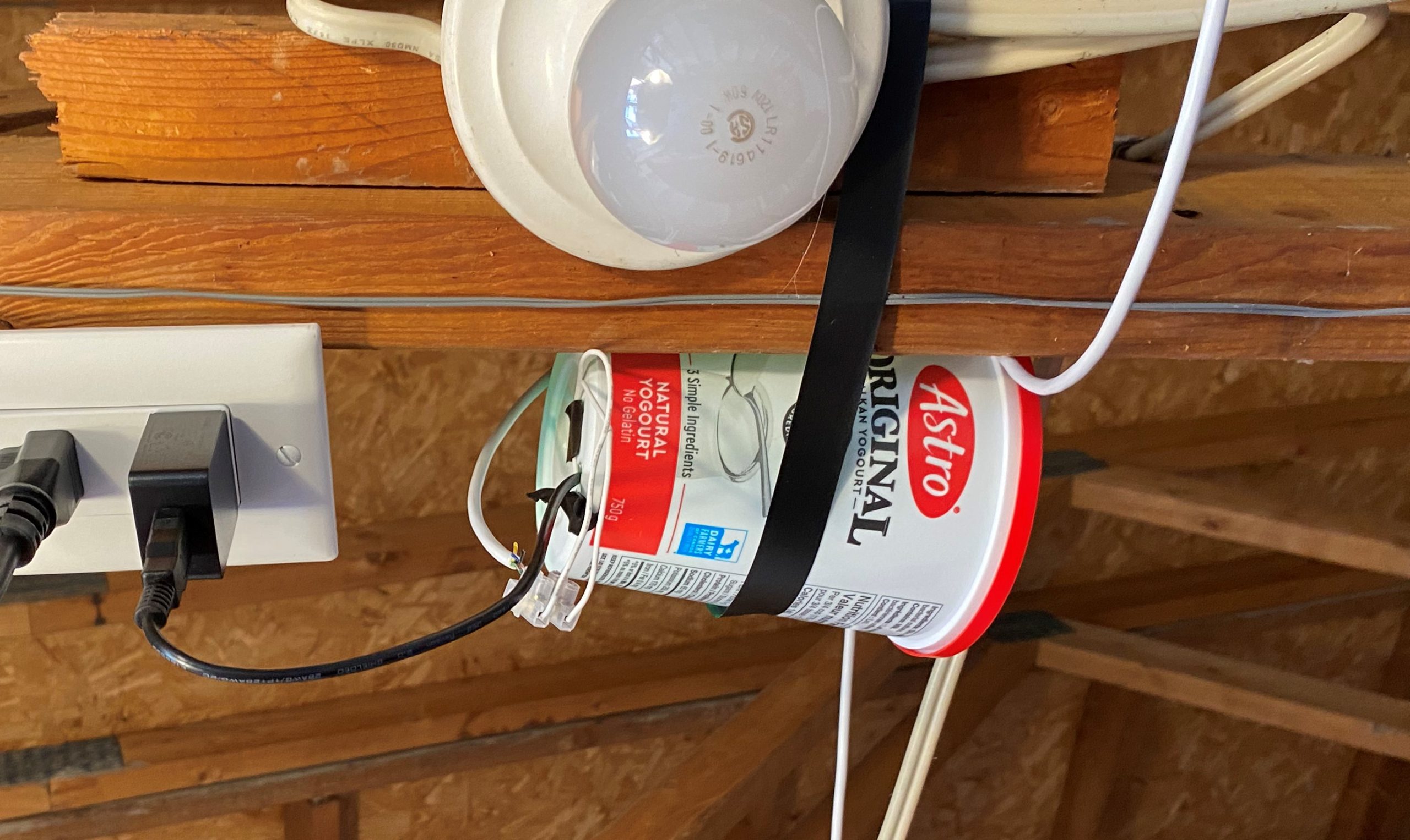
A more recent addition to the collection, and not related to a specific task, but just some extra code I’ve implemented for logging and status. When we moved into our rental, we were given one of the large garage remote controls. But, especially in the summer, my wife and I mostly cycle, and these remotes are bulky and annoying. We bought one of the smaller remotes, but my wife and I are often out separately. So now we can open the garage via Wi-Fi.
The ESP runs a basic web-server, just waiting for a request to open the garage door. I need to still install a sensor and feed this data back to the server. And if I’m doing that, I might as well monitor the temperature in the garage too…
You see a yoghurt container, I see the perfect container for a microcontroller, a relay and some LEDs
Other Tasks
Beyond the local devices actively pushing data to the server, there are a number of tasks that get run for ad-hoc items.
Outside Temperature
Lacking an outside connected thermometer, I instead choose to just pull data from the weather api every 20min.
Data plotting
Instead of learning how to plot data on the fly in a web-friendly format. I chose the lazy route I already had experience with, which is using python’s Plotly library to generate an interactive html graph. And because doing this on the fly on a raspberry pi can be very slow, I just do it every few hours, and supply the last generated one when requested. This can be improved. (UPDATE: I installed grafana, see screenshot at the end of the post)
NAS Wake/Sleep
I have a NAS downstairs, it can be a bit noisy. I only ever need to use it at night, which is also when it needs to be on to perform internet backups. So I get this task to use WoL to start it up in the evening, and an ssh command to put it to sleep in the wee hours of the morning.
Get external IP
At some stage I started setting up cloudflare to redirect a domain to my homeserver. I never completed this, but I did write a script to monitor our external IP address and update me via e-mail whenever it changed.
Strava
Earlier this year, Strava added Squash to their list of supported activities. I’d done a lot of squash activities, that were listed as Workouts. So I went about setting the record straight, using the Strava API to update all my previous activities that matched the criteria to be Squash. With all that done, I extended it to start adding weather data to my outdoor activites and ensuring that all my future squash activities get listed as such (Garmin don’t support Squash, so my activity still gets sent to Strava as a Workout, and then the script updates it). So now I have a web-hosted server that Strava notifies whenever I (or other people) complete an activity. My raspberry pi polls this server occasionally and runs scripts locally to determine if anything needs to happen, and then update activities as necessary.
You have to give whatever’s accessing the Strava API a name, thus StraWeer was born
Express Entry
At one stage we had an application in for Canadian Express Entry. They released new results usually once a week, but not at fixed times, and occasionally more than once per week. So I set this task to scrape the site where they posted the results and e-mail whenever it got updated with the latest results. Sometime after it was no longer applicable to us, the website was updated to no longer provide the information with a standard http request. So I stopped running it.
I started on this project a long time ago, and would often not look at the code for months or years, then update it to do something I wanted. It certainly has a lot of shortcomings, a lot of opportunity for improvement, and would do well to better implement a lot of things I’d consider good programming practice these days, but were not top of my mind at the time. That being said, it works. The fact that I only have to do something to it when I want to make an improvement is evidence of this. My biggest ongoing concern is when the Raspberry Pi’s SD card is going to pack up :D
And then
Most of the code that runs on the Raspberry Pi is available in the below repo. I’m still updating it with some of the Strava integration stuff, but I need to do some more improvements first
This is probably the easiest modification you can imagine, although it took a bit of time to figure out. When we imported our car from the US to Canada, we had to get Daytime Running Lights installed, as the US spec vehicles did not have this standard.
The DRL requirement is pretty broad, but basically, whenever the car is moving, your vehicle is required to have ‘some’ front facing lights on. The standard modification is to purchase a kit like this, which is just a relay you put in parallel with your existing headlight (or parking light) relay, and then wire up to turn on with your ignition.
Not particularly complicated, but it’s extra stuff you have to mount in the car, and connect etc. Surely there is a better way? Even in the US, we already drove the car with the headlights on the whole time. The car automatically turned them off when you stopped the car. But the DRL requirement means that even if the light switch is in the OFF position, the lights must still come on when driving. Lucky for me I had gotten hold of the service manual for our car, and was able to dig through the limited wiring diagrams provided.
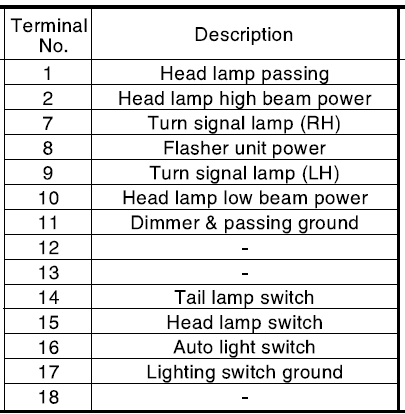
Wiring Diagram for Light Switch
Signal names
From the above diagrams we can see that when the switch is in the ON (ll) position, the system connects “Lighting switch ground” to “Tail lamp switch”, “Head lamp switch” and “Auto light switch”. And when the switch is in the Parking Lights (l) position, it connects “Lighting switch ground” to “Tail lamp switch” only. When it’s OFF, no connections are made.
I couldn’t find the full circuit diagram for the lighting switch, but the circuit diagram for the Auto Lighting circuit (which our car doesn’t have) seemed like a good starting point.
Auto Lighting Circuit Diagram
If we just ignore all the connections to the Auto light unit, we probably get a good idea of the circuit. The key take away is that battery power is only provided to the headlamp relay when the ignition is on. So in theory, if we just short “Lighting switch ground” to “Head lamp switch”, the lights will come on and off with “IGN2”.
Another thing to keep in mind, is that this modification would then not result in your tail lamps being illuminated. This is fine from a legal perspective, but means that at night, you must ensure your light switch is in the ON position.
I considered just connecting the “Tail lamp switch” to “Lighting switch ground” at all times as well, but it leads to complications if you want to use your parking lights. On the Hyundai Tucson, the parking lights come on and off with the tail lamps. Additionally, default behaviour is that when you turn the car off, no matter what position your light switch is in, all lights turn off when the car is locked. Including parking lights. If you want the parking lights to stay on, you have to leave the driver’s side door open, turn the lights from ON/Parking to OFF, and then back to ON/Parking. Then when you close and lock they’ll stay on. Were I to permanently connecting the “Tail lamp switch” to “Lighting switch ground”, there would be no way to get the circuit into an OFF state, so that I could then activate the parking lights after I locked the car. It’s not that I’ve ever used my parking lights for their intended function, but I still have to pass an Ontario Safety inspection, and it’s not clear to me whether they check actual functionality, or just that I have working lights in the parking lights.
Instructions:
Remove steering column footwell cover (2 screws)
Remove steering wheel upper cover (clips into lower cover)
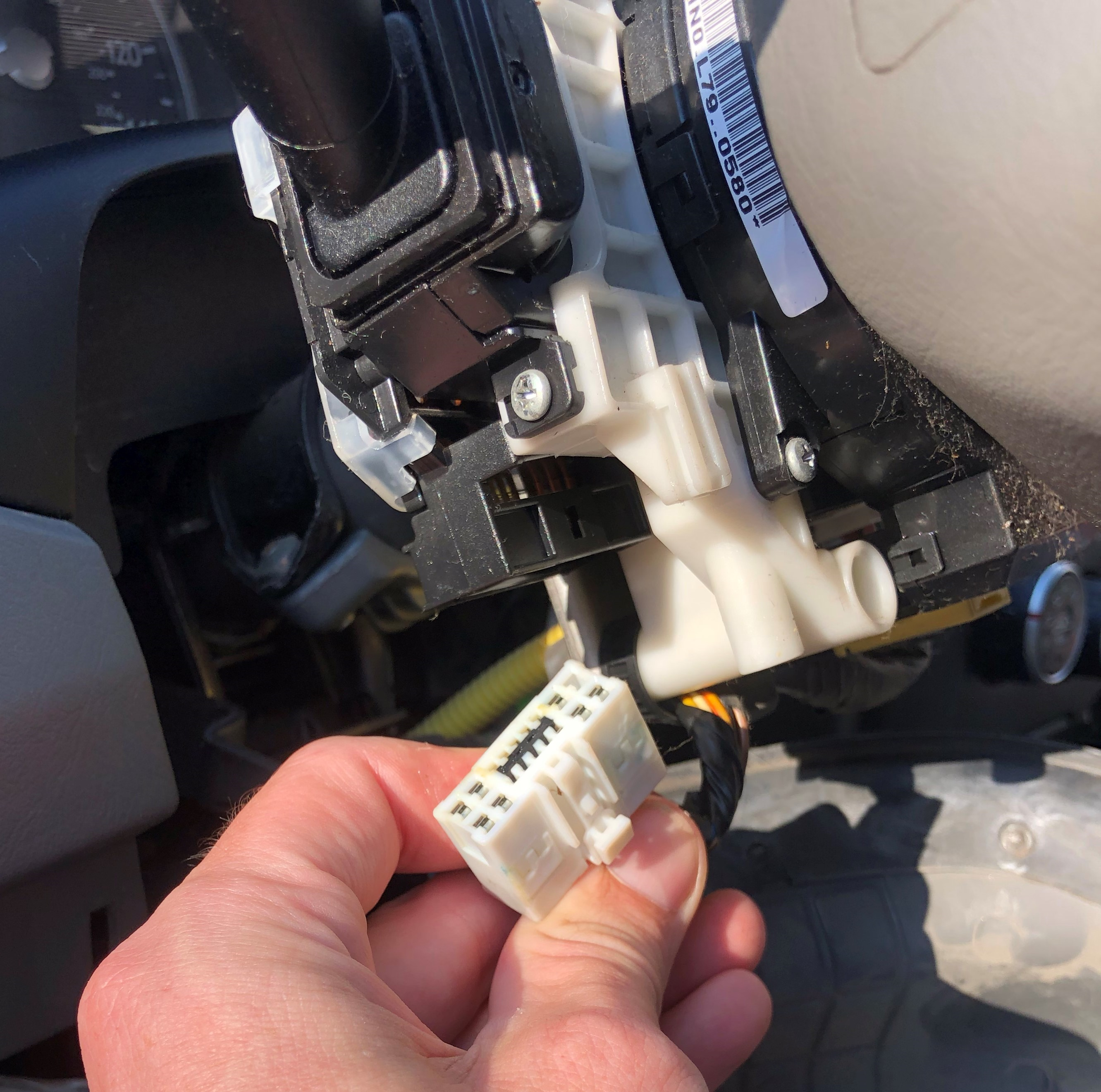
Unplug Lighting Switch connector on left hand side.
Head lamp wiring harness connector
Identify “Head Lamp Switch (15)” and “Lighting switch ground (17)” wires in connector.
Connector wiring diagram
To confirm you have correctly identified the wires:
Use a multimeter to confirm that pin 17 is shorted to vehicle ground.
Switch the Light switch to the OFF position and confirm no short between 14, 15, 16 and 17
Switch the Light switch to position l and confirm short between 14 and 17, but not between 15, 16 and 17
Switch the Light switch to position ll and confirm short between 14, 15, 16 and 17
Using whatever your preferred method is, make a permanent connection between pins 17 and 15. I took some of the insulation off the wires behind the connector and soldered a jumper cable in-between.
Other non-solder alternatives are available: referral link
Reconnect Lighting Switch connector.
Test lighting works as expected:
With ignition on, Headlamps are on in all lighting switch positions (OFF, l and ll)
With ignition on, Tail lamps and Parking lights are on in Positions l and ll
Preface: This was originally drafted in September 2020, and is only being published ~2 years later. I can’t remember my exact mood when I drafted this article, but apparently it was one of those days. It was also not the first time I’d experienced this issue. I hope posting it here will allow me to not experience this issue again, and help someone else who befalls a similar misfortune.
I hate everything. That’s right. Everything! ARGH! Cue continuos shouts into the void.
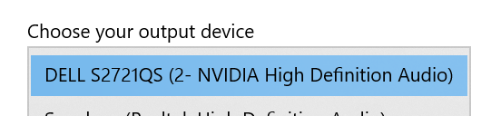
Issue: Laptop won’t output audio over HDMI. There is no setting anywhere that seems to allow you to output to HDMI, even though you could swear you’ve done it before. Also every ‘solution’ on the internet tells you to do something you’ve already done or change a setting that doesn’t exist.
Device: Asus FX502VM, Windows 10, GeForce GTX 1060