Install Flash Drive in A110

The standard 8GB SSD that comes standard in the Acer Aspire is a bit crappy. It’s rather slow, and obviously 8GB isn’t particularly much space. I knew of others who had installed Flash Drives in their netbooks and figured I’d do the same. I couldn’t find any posts about people who had done it, but I did find Tnkgrl who had added a USB bluetooth device to hers and a guy over at WRP & CW – Radio Shack who added a USB fingerprint scanner to his.

They both used different places on the motherboard to access extra USB ports. Both of them work without disabling any of the other USB ports. Tnkrgrl made use of some pins under where the Wi-Fi card is situated, and the Radio Shack hack some points near the CPU. I wasn’t too keen to fiddle with a soldering iron near the CPU, so instead chose to use Tnkgrl’s post for reference. I managed to solder the power wires in quite easily but really battled to get the data wires in place. My soldering iron is unfortunately not built for finicky work like this, so I eventually gave up and decided to use the data points that Radio Shack used.

I purchased a 16GB Kingston Data Traveller G2, stripped it of it’s casing and soldered the appropriate wires to it. Putting everything back together and booting up in Linux revealed the drive to be in working order.

What I plan to do now is to install Windows XP onto the SSD and Linux onto the Flash Drive. Although I am getting very used to Linux, I still have several Apps that I just can’t get to work in Linux, and can find no alternatives.

Below I show how to take apart the Acer. When I did it I followed this guide by Tony Smith.

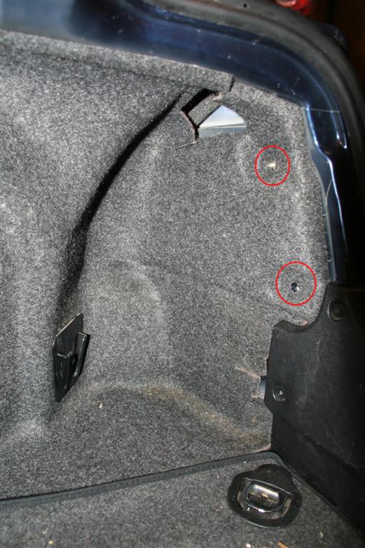
First remove the battery and unscrew the 6 screws on the underside of the netbook. I have circled them in the following picture. You also need to remove the two rubber feet near where the battery goes, and remove two screws from underneath them.img_4192
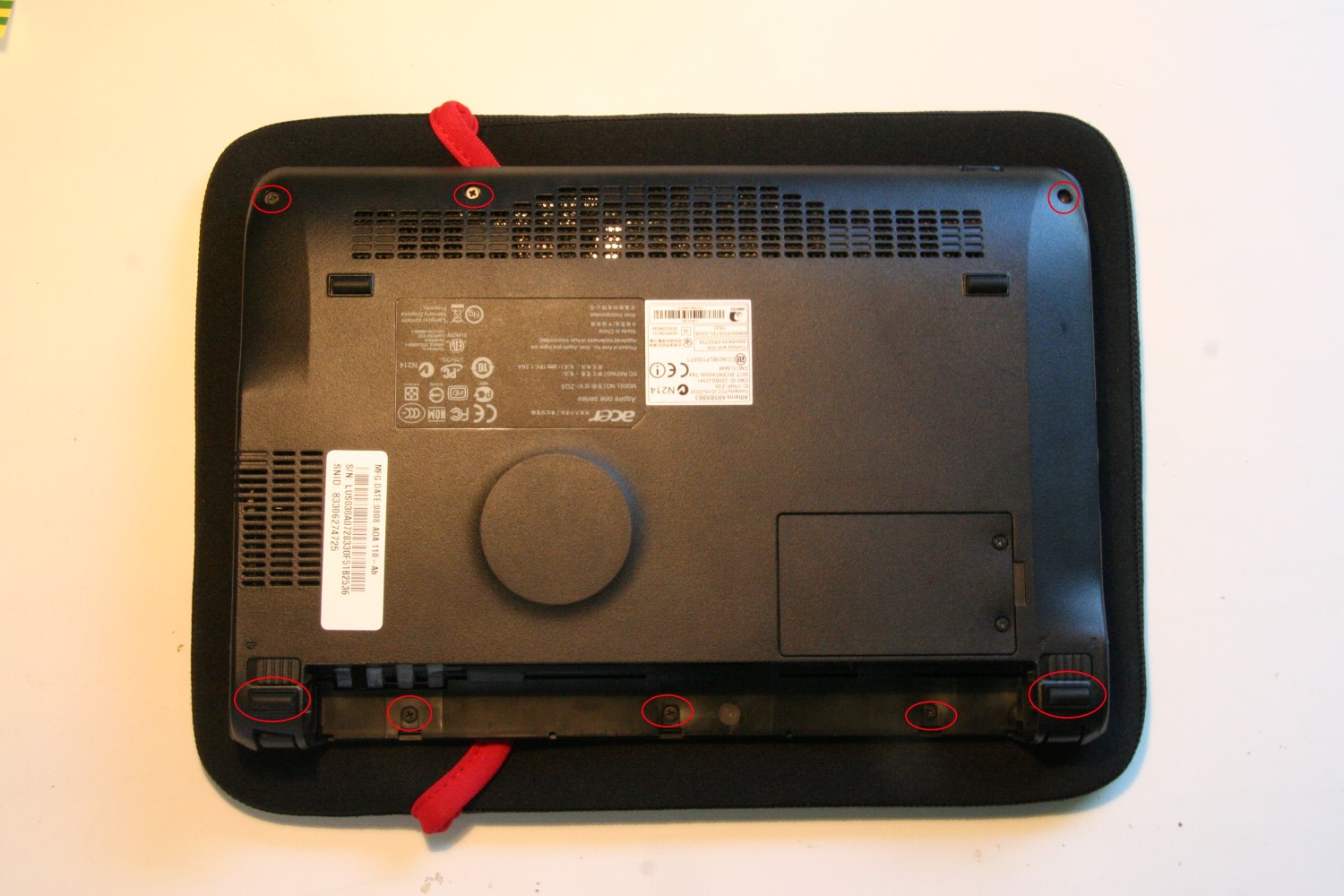
Turn over the netbook and lift open the screen. The keyboard is held in place by 3 spring loaded clips along the top of the keyboard. I have circled them in the next picture. Using a flat head screw driver or credit card push these in one by one. As each one is pushed in, the top of the keyboard should lift slightly. Once all three of the clips have been pushed in, raise the top of the keyboard slightly and pull it towards the screen. This should allow the hooks at the bottom of the keyboard to come loose. Underneath, the keyboards wires go to the motherboard. It is fairly simple to release the catch on the cables clip on the motherboard, and free it form the netbook.img_4196
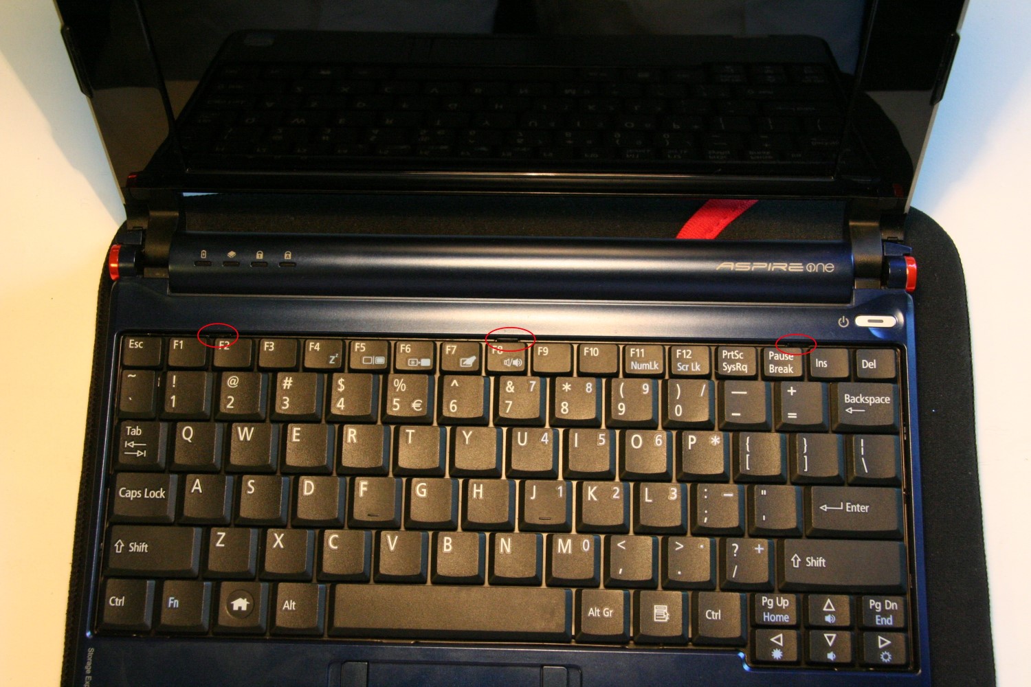
Next you have to remove 6 screws that hold the casing together, they have been circled in the following picture. You also need to unclip and release the cable that goes from the touchpad to the motherboard.

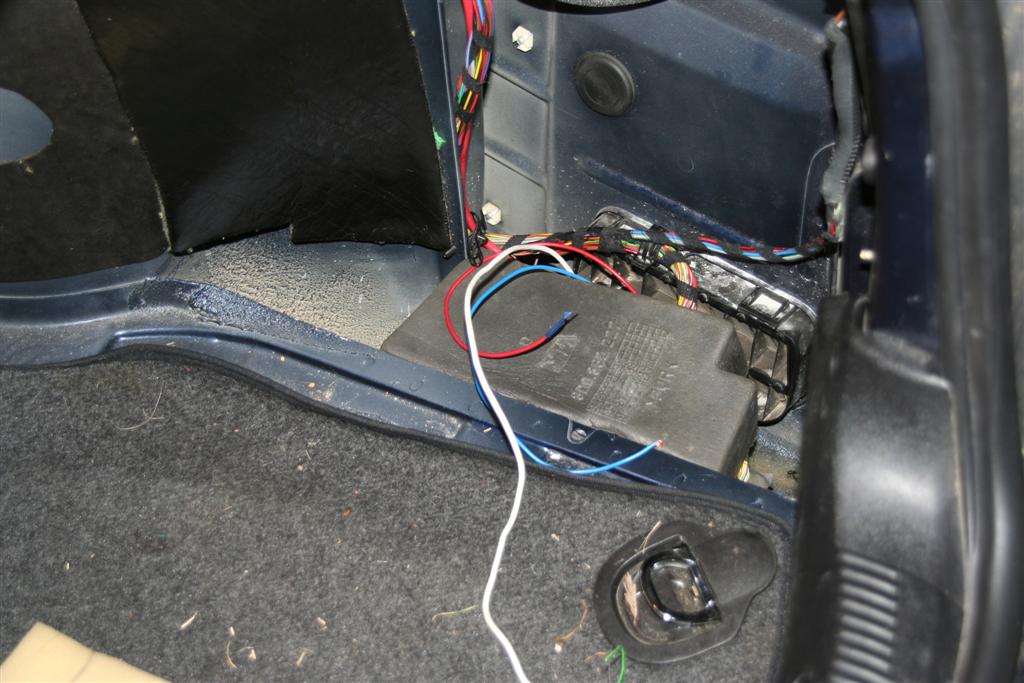
Next part isn’t that nice. The top part of the casing clips into the bottom half with a series of clips around the edge. You need to stick your screwdriver or credit card in on one end and slowly work your way around the edge of the netbook unclipping it. Once they’re all unclipped you unhook the top parts from just below the screen hinges. You should now have the motherboard in full view.img_4200
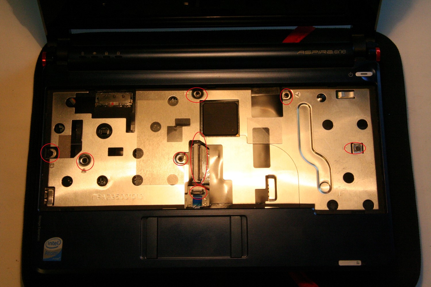
If you wish to remove the motherboard you must undo the two screws in the lower part of the image above. This will allow you to first remove the wifi card. You must also undo the clip that holds the SSD’s cable in place on the motherboard, and also unplug the pug that carries the wires to the screen in the top right of the screen. To make life easier you should also undo the two screws that keep a hook in place in the top left. This acts as part of the hinge mechanism and to hold the motherboard in place. Underneath the motherboard is another wire harness which carries wires to the board on the right of the laptop.

If you wish to install more/new RAM, this is quite easy, you need simply plug it in to the open slot on the underside of the motherboard.img_4201
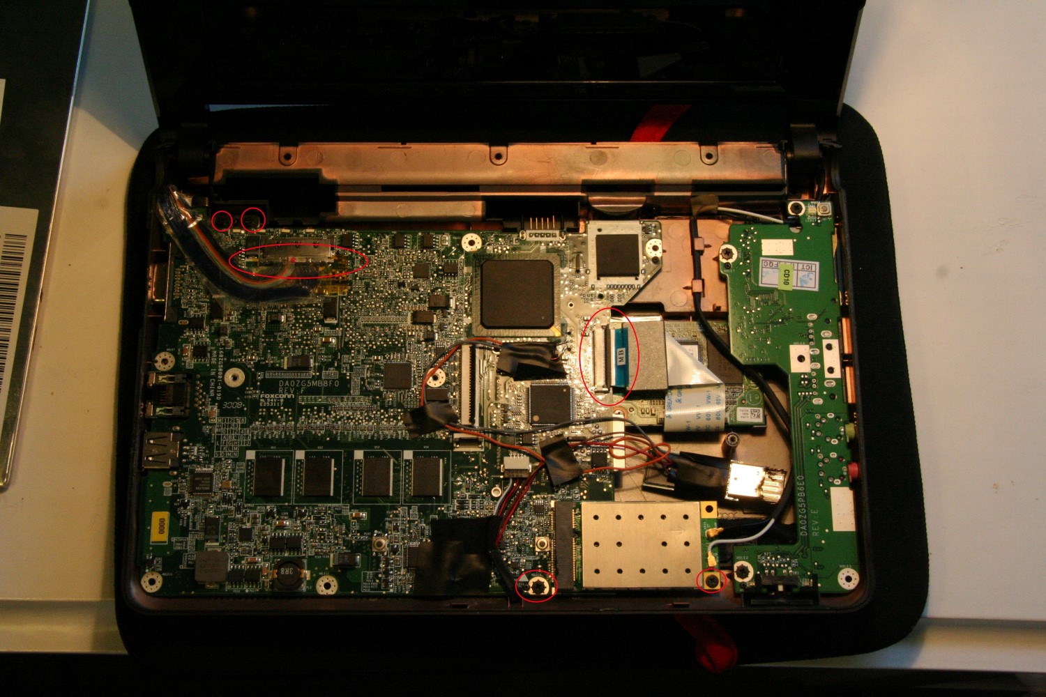
In this image you can just see where my two data wires solder onto the motherboard by the CPU. At the place there are two columns of solder points. The left column has 4 pins and the right column 5. On the left column the first point (ie the top point) is the Ground, the second point Data+, third point Data-, and fourth (bottom) point 5V+. In my picture I only used the data points.This image from the aforementioned Radio Shack shows the points better. This image from Tnkgrl shows the two power points I used for my Flash Drive, and also the other two Data points that can be used.

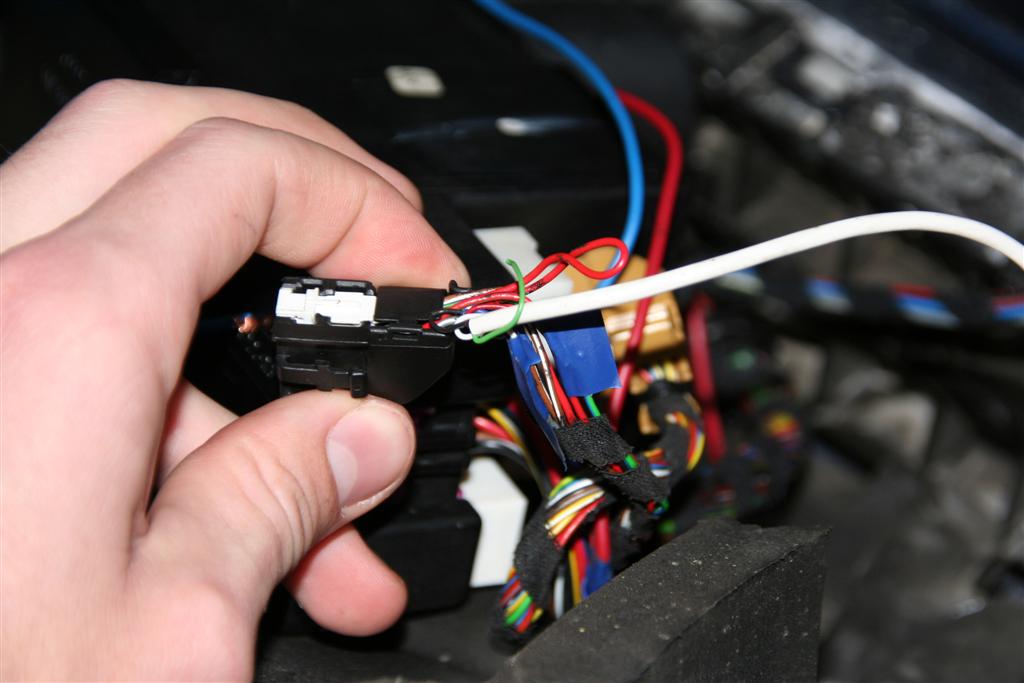
For the four points on the Flash Drive itself. Lying the flash drive down with the contacts on top, and to the right. In order from top to bottom, the contacts are: 5V+, Data-, Data+, Ground. I just stashed the flash drive to the right there,forwards of the SSD where there was some space. Because these are just standard USB ports they can be used to install any standard USB device. The guy at Radio Shack actually installed a tiny USB Hub into it, allow new additions to be installed relatively easily.

Audi Remote Control

So, when I got my car (’96 Audi A4 B5) the remote control for the central locking didn’t work. We replaced the batteries and did a series of tests to try sort it out but nothing worked.

We took it in to the local Audi dealership who after a morning of having it returned it to us with a quote for R8000 (excl). We said thank you and I have used the key ever since.

It seems that something went wrong with the Infra-Red system my Audi used (I know from 1997 they switched to RF remotes) and the previous owner never bothered to fix it.

If your Audi came out before the IR remotes, this approach should still work, if it came out after the RF remotes, check here.

Now the Audi’s whole security system, the alarm, the pump for the central locking etc are all contained in one neat little box located in the boot under some panels. So although 90% of my box still worked (everything except the infrared circuitry) they would have to replace hte entire unit. Thus the huge cost. I’ve seen 2nd hand units advertised for about R3000, so it is just an expensive component.

So recently I got thinking, couldn’t we just try and install a conventional wireless system around the current system.

Because the infrared system was stuffed, we decided to go at it a different way, and use the signal that gets sent to the alarm system when you manually unlock the driver’s door.

This invloved taking the panelling off and finding the wires that go from the lock to the alarm system. 3 wires were found, a brown one (we think it’s some form of check to see if the door is open or closed) and the two important ones, a red & brown cable witch is shorted with the car’s earth when the key is used to lock the car, and a grey & white cable for unlocking.

To get at the security box in the car open the boot and remove the mats covering the side wall and bottom area off to the right of the boot. I had to remove a little storage box by just lifting it up and unclipping it. There are also two plastic caps which keep the mat in place, remove those, then you just need to use a bit of force to work the carpet out from behind the plastic fascia. You shouldn’t have to unscrew anything.img_0853-large img_0849-large img_0852-large

Once removed you should see a foam box to the right, lift the cover and a plastic box should be lying there. There are 3 wiring harnesses, the two outer ones can be pulled straight out, but the middle (power) one needs a screwdriver or something to unclip. There is also the air pipe which can just be pulled off. You can then quite easily remove the security box. This is just to make soldering easier.img_0848-large

Of the two outer plugs, one is smaller than the other. This is the one that takes signals from the lock in the driver’s door. You will find two wires that correspond to the two we found in the driver’s door. The grey & white and red & brown ones.img_0846-large

And voilĂ !

Connect these onto a remote control receiver and you’ve got yourself a new remote control.

Power for your receiver can be taken from the middle wiring harness. Check your polarity with a multimeter, but for me the brown cable was earth (which I used as the earth for the lock and unlock signal as well) and the red one next to it was positive. This gives you the necessary 12V.img_0847-large

I haven’t connected my remote control yet, as I’ve had to shop around for a decent one at a cheap price. I eventually found this on ebay for R240. At a local security shop they sold a 3 channel receiver (for garage doors) for R310 and a remote with two buttons is R150 rand. Those are code hopping ones, which are more secure than the ones I bought, and will work fine in a car.

note: When you use the key, turning it once turns off the alarm, and physically unlocks your door. That means that if you push your remote control once, it will turn off the alarm and NOT unlcok your front door. If you turn the key twice in succession it unlocks all the doors. Likewise, pushing the remote’s button twice will unlock all the doors.

If someone manages to hack the infrared section of the circuitry, you would not have this problem. I may get round to looking through it one day, but at the moment this works :)

When I get my remotes I will see if I can build a small circuit to send two signals instead of one, so I don’t have to push twice each time.

I have already soldered all the wires in place that I need to install my receiver, and have checked that they work by shorting them. I will repost once I have received my package and installed it.

Audi Radio codes :(

So, I have a 1996 Audi A4 B5 1.8. It comes stock with a Blaupunkt radio. The radio itself says it’s a Gamma CC, whereas everything on the internet points it towards being a Delta CC.img_0241-largeAnyway, effectively my car’s battery was replaced, which sends the radio into lock down mode. Enter a 4 digit pin, and you can continue using the radio. The code for said radio comes with the radio’s manual, with neat instructions about what to do with the code. It recommends cutting it out and storing it in a safe place, something the previous owner of my car did with much enthusiasm.img_0838-largeAnyway, I have effectively been left with a radio that I can’t use. This was two days before I was supposed to take a 3000km tour in said car. I spent hours on the internet searching for ways to get the code. And was blocked at every way.

In the end I discovered that the only way to get the code, is to take your car to Audi, they charge you for their minimum work time (roughly R275) and give you your code, after 5min.

I don’t like to think of myself as stingy, but to pay R275 (the cost of a low end frontloader) for them to do this goes against who I am. It didn’t help that my previous dealings with the local Audi dealership left us on unsavoury terms.

Apparently it is possible to get your code from Blaupunkt themselves. I haven’t tested this myself, but Maple Audio can allegedly get your code for you if you supply them with the radio’s serial code. For the pricely sum of GBP25 that is.

But yet again here I was, stuck on a Friday night without a radio. I decided the best plan would be to replace the radio with an old radio we had lying around at home. This I proceeded to do on Saturday morning.

Fortunately I had had the foresight to get a local car audio place to remove the radio for me, as I found myself without a means to remove the radio. After looking at the mechanism, you can take the radio out with some steel wire if need be. I have a nail file in a knife which also works quite nicely.

Simply push whatever “key” you are using with the point on the outer side of the hole and push the key in and shift it inwards. You can understand the way it works by looking at the picture.img_084211-largeSo, unlike on previous cars I’ve dealt with, the Audi’s radio has three wiring harnesses that plug a veritable array of non-colour coded wires into the radio. Most of the other radios I’ve dealt with adhere to a standard wiring system, with different colours symbolising which speaker the wire leads to, what is positive. negative etc. Not on this one.

Anyway, after a while of fiddling round I figured out a system that would work.

The radio I was installing is a cheap radio with four wires. Left, Right, Positive (power) and common (for the speakers). Simple enough.

Because I didn’t want to just chop off all the wiring harnesses on the car’s side, I had to figure out a method of making plugs that would fit, that I could solder onto the radio’s wires. I ended up using little wiring plugs that I cut to size with a pair of side cutters.img_0245-largeI hooked up two plugs for each of the left and right wires, so I could have sound front and back. I also found a washer and screw to attach an earth to the back of the radio.

The car had a dedicated earth plug, but I found that making use of it only supplied my radio with 9V, so instead I used one of the earth’s on the wiring harness.

Now on the Delta CC radio there is wiring diagram of what all the pins are supposed to link up to, unfortunately some of them are missing, which I only noticed after having soldered and wired all my plugs.img_0239-largeI eventually ended up only connecting the front speakers, because for some reason only they would work, even though I feel that the back speakers should have worked with the way I had wired it. But in any case.img_0240-largeI used the point corresponding to pin H for the negative (earth) on my radio and pin B fo the positive. I checked the voltage before hand to ensure there was 12V and also chose this connection as it supplies the 12V even with the ignition off.

I initially attempted to use i -> ix points to hook up the sound but couldn’t get it work. Partly because my wiring harnesses were missing the contact points ii & viii. I ended up using points A -> D and just hooking up the front speakers. Because I wasn’t going to play the music too loudly, I didn’t bother to test which was the positive and negative of the speakers and just hooked up 1 & 2 as common, and 3 & 4 as the positives for the left and right speakers.

If you are installing a permanent radio, it is advised to check the polarity of the speakers. This can be done by removing the speaker’s covers and attaching a 1.5V battery to it. If the speaker bulges outwards as you attach the battery, you have the polarity correct. If the speaker membrane retracts, switch the polarity.

Now, the aerial. This posed a particular problem, why? because the radio aerial connector on the Audi is not the standard one that I know. So, to overcome this, I just didn’t bother hooking it up. I was originally going to use an FM transmitter with an MP3 player to listen to music, but due to this problem, I instead opted for one of these cassette adaptations (that I had lying around the house), which allow a 3.5mm audio input.

Some time in the future I’ll figure out how to correctly connect the rear speakers as well, and post it here. Any questions feel free to post below.

Sorry for the long windedness of this post. Once I get going I tend not to stop too soon.

This system worked for me for my entire journey, only decision I have to make now is what radio to buy :) Also, my next plan will be to build a cruise control system into my car.img_0249-large