The standard 8GB SSD that comes standard in the Acer Aspire is a bit crappy. It’s rather slow, and obviously 8GB isn’t particularly much space. I knew of others who had installed Flash Drives in their netbooks and figured I’d do the same. I couldn’t find any posts about people who had done it, but I did find Tnkgrl who had added a USB bluetooth device to hers and a guy over at WRP & CW – Radio Shack who added a USB fingerprint scanner to his.
They both used different places on the motherboard to access extra USB ports. Both of them work without disabling any of the other USB ports. Tnkrgrl made use of some pins under where the Wi-Fi card is situated, and the Radio Shack hack some points near the CPU. I wasn’t too keen to fiddle with a soldering iron near the CPU, so instead chose to use Tnkgrl’s post for reference. I managed to solder the power wires in quite easily but really battled to get the data wires in place. My soldering iron is unfortunately not built for finicky work like this, so I eventually gave up and decided to use the data points that Radio Shack used.
I purchased a 16GB Kingston Data Traveller G2, stripped it of it’s casing and soldered the appropriate wires to it. Putting everything back together and booting up in Linux revealed the drive to be in working order.
What I plan to do now is to install Windows XP onto the SSD and Linux onto the Flash Drive. Although I am getting very used to Linux, I still have several Apps that I just can’t get to work in Linux, and can find no alternatives.
Below I show how to take apart the Acer. When I did it I followed this guide by Tony Smith.
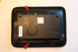
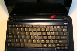
First remove the battery and unscrew the 6 screws on the underside of the netbook. I have circled them in the following picture. You also need to remove the two rubber feet near where the battery goes, and remove two screws from underneath them. Turn over the netbook and lift open the screen. The keyboard is held in place by 3 spring loaded clips along the top of the keyboard. I have circled them in the next picture. Using a flat head screw driver or credit card push these in one by one. As each one is pushed in, the top of the keyboard should lift slightly. Once all three of the clips have been pushed in, raise the top of the keyboard slightly and pull it towards the screen. This should allow the hooks at the bottom of the keyboard to come loose. Underneath, the keyboards wires go to the motherboard. It is fairly simple to release the catch on the cables clip on the motherboard, and free it form the netbook.
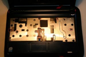
 Next you have to remove 6 screws that hold the casing together, they have been circled in the following picture. You also need to unclip and release the cable that goes from the touchpad to the motherboard.
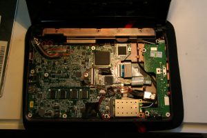
Next part isn’t that nice. The top part of the casing clips into the bottom half with a series of clips around the edge. You need to stick your screwdriver or credit card in on one end and slowly work your way around the edge of the netbook unclipping it. Once they’re all unclipped you unhook the top parts from just below the screen hinges. You should now have the motherboard in full view. If you wish to remove the motherboard you must undo the two screws in the lower part of the image above. This will allow you to first remove the wifi card. You must also undo the clip that holds the SSD’s cable in place on the motherboard, and also unplug the pug that carries the wires to the screen in the top right of the screen. To make life easier you should also undo the two screws that keep a hook in place in the top left. This acts as part of the hinge mechanism and to hold the motherboard in place. Underneath the motherboard is another wire harness which carries wires to the board on the right of the laptop.
If you wish to install more/new RAM, this is quite easy, you need simply plug it in to the open slot on the underside of the motherboard. In this image you can just see where my two data wires solder onto the motherboard by the CPU. At the place there are two columns of solder points. The left column has 4 pins and the right column 5. On the left column the first point (ie the top point) is the Ground, the second point Data+, third point Data-, and fourth (bottom) point 5V+. In my picture I only used the data points.This image from the aforementioned Radio Shack shows the points better. This image from Tnkgrl shows the two power points I used for my Flash Drive, and also the other two Data points that can be used.
For the four points on the Flash Drive itself. Lying the flash drive down with the contacts on top, and to the right. In order from top to bottom, the contacts are: 5V+, Data-, Data+, Ground. I just stashed the flash drive to the right there,forwards of the SSD where there was some space. Because these are just standard USB ports they can be used to install any standard USB device. The guy at Radio Shack actually installed a tiny USB Hub into it, allow new additions to be installed relatively easily.
