
I haven’t had a bedside lamp for a while. I just never bothered. So, on seeing a competition on Hackaday for Circuit Sculptures, and having a sudden surge of inspiration, I decided to give it a go.
My final entry can be found on Hackaday.io here, and in tandem I uploaded all the files to Github here. There’s a brief demo video below, and full gallery at the end.
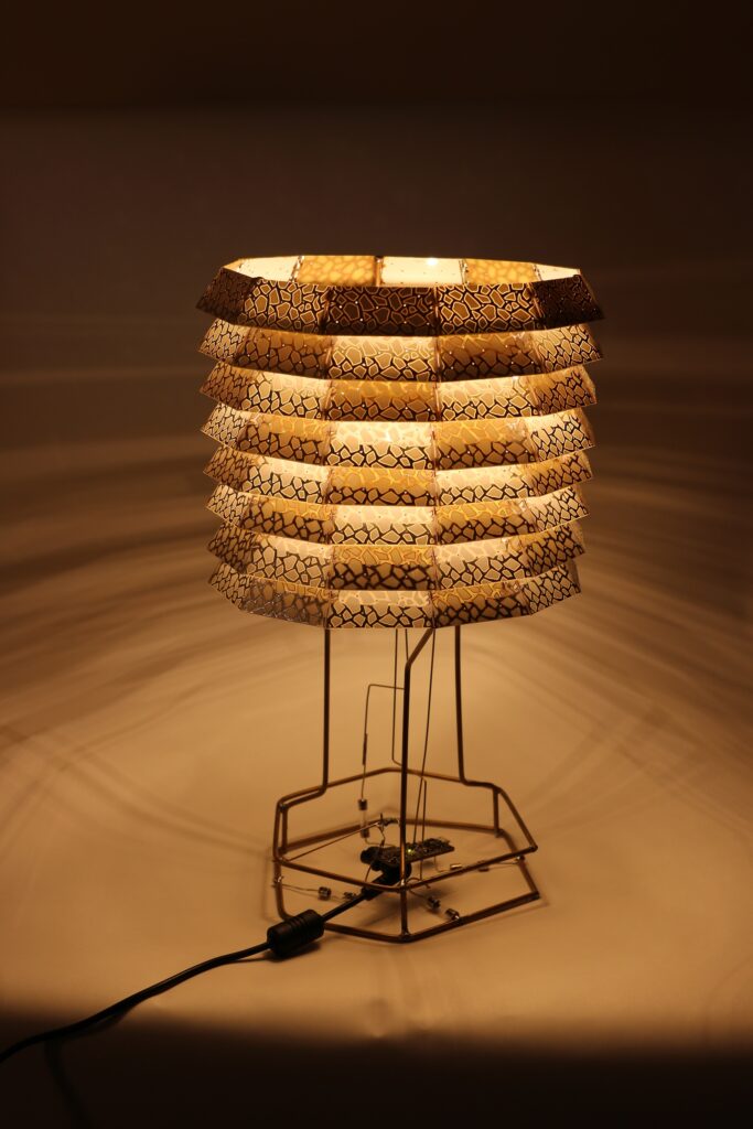
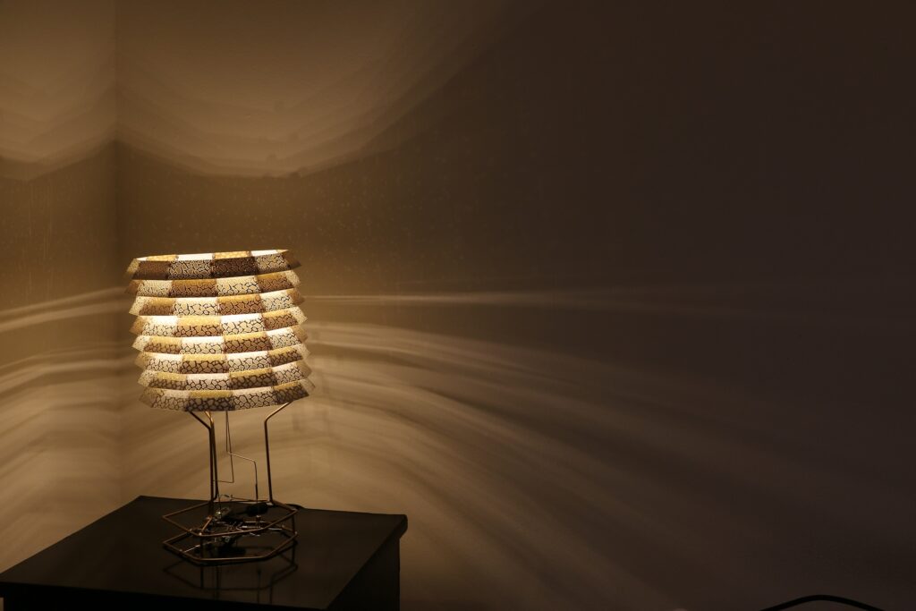
I only decided to do something a few weeks after the competition had started, so I decided to go fast, make easy decisions and not worry about efficiency, or cost too much. LEDs were the obvious choice for light source, but LEDs are bright and directional, not ideal for a lamp. And so I got it into my head to make a lampshade out of PCBs.
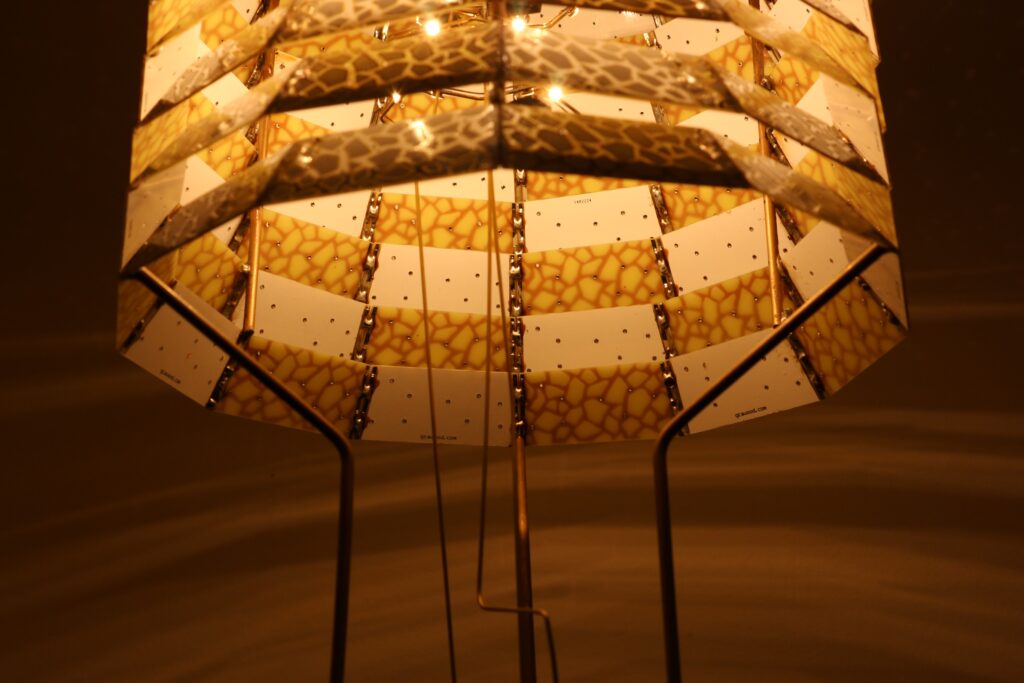
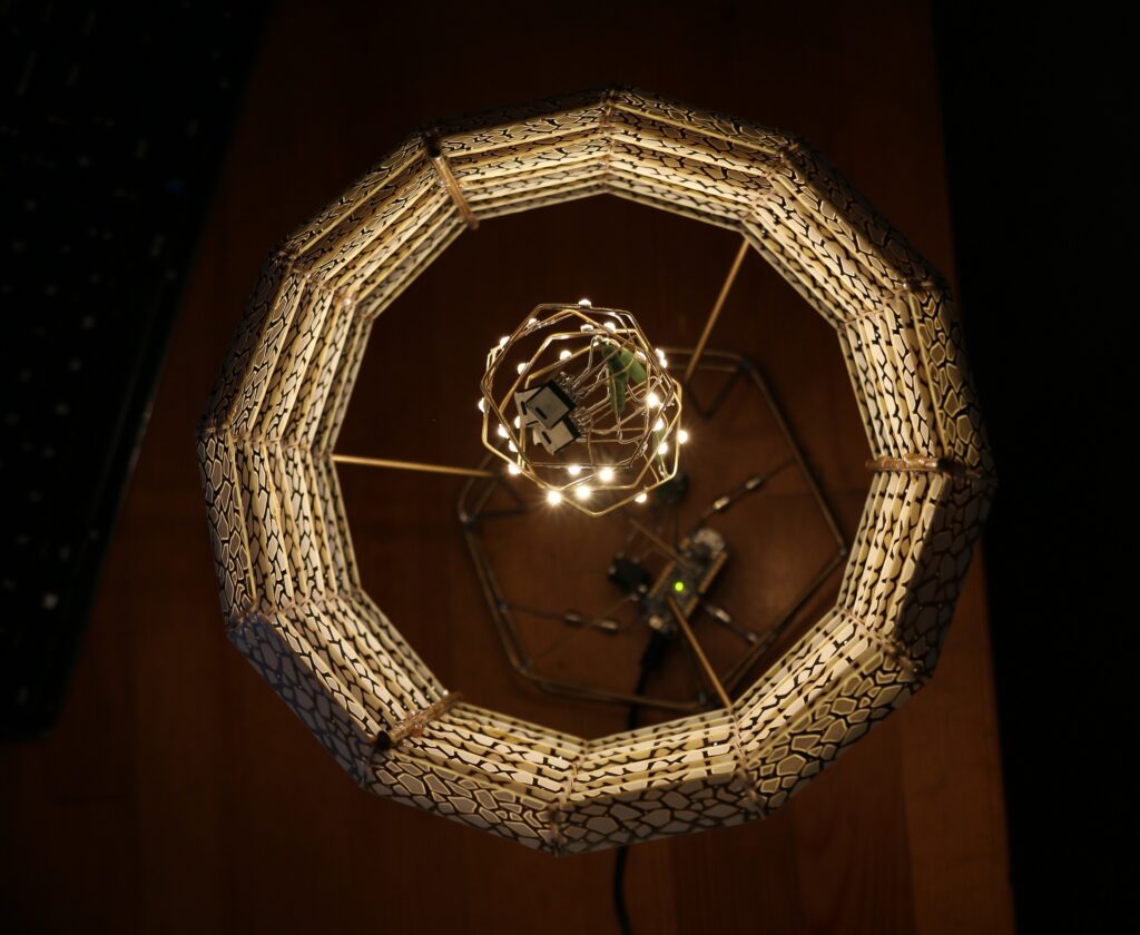
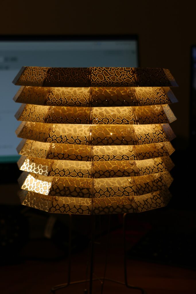
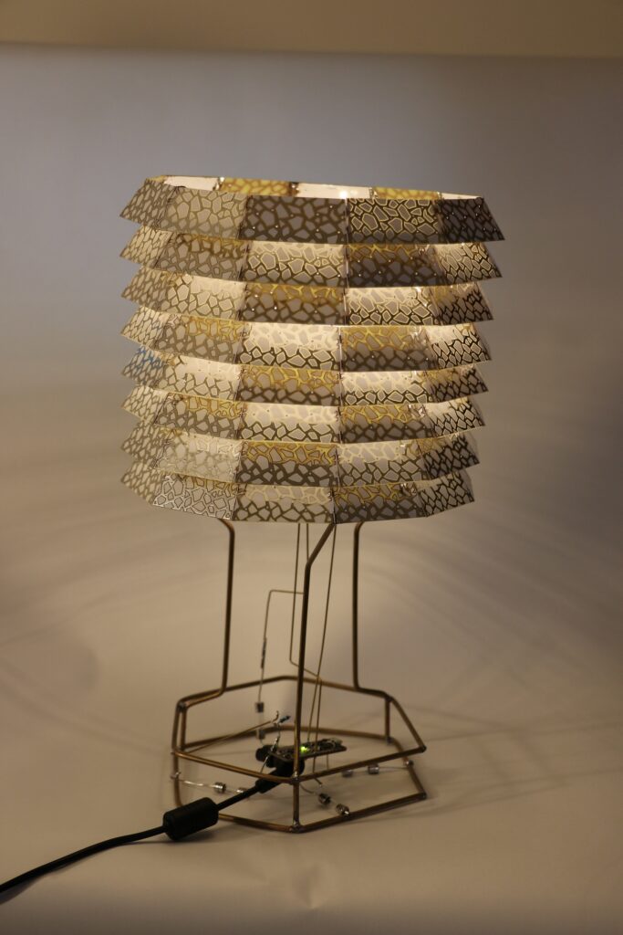
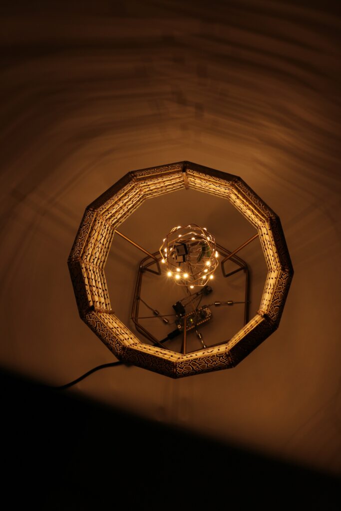
With the number of board fabs offering $5 deals on various PCB sizes and numbers, I figured I’d be able to work something out that wouldn’t be too expensive. I went through a number of iterations on various shapes and sizes before settling on a stacked dodecagon design. The layers would be slightly angled, to allow light to reflect off and hopefully out.
Performing some size optimization to fit into Seeed Studio’s 100x100mm cheap design limitation, I ended up with 8 panels per board. I need 12 panels per layer, and size wise I was hoping for 8 layers. This is 96 panels. Seeed gives you 10 boards, so for one order I’d get 80 panels. Knowing I’d need two orders then, I decided to experiment a bit.
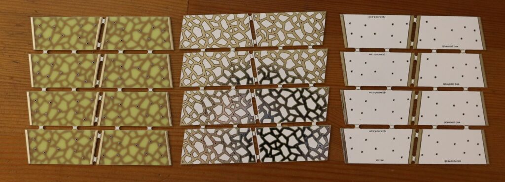
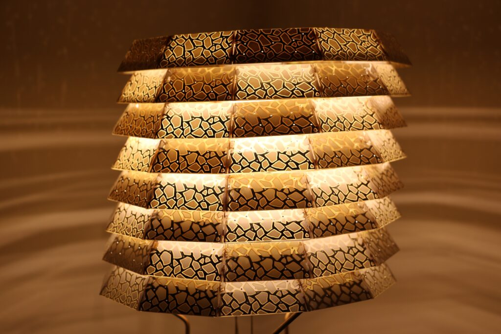
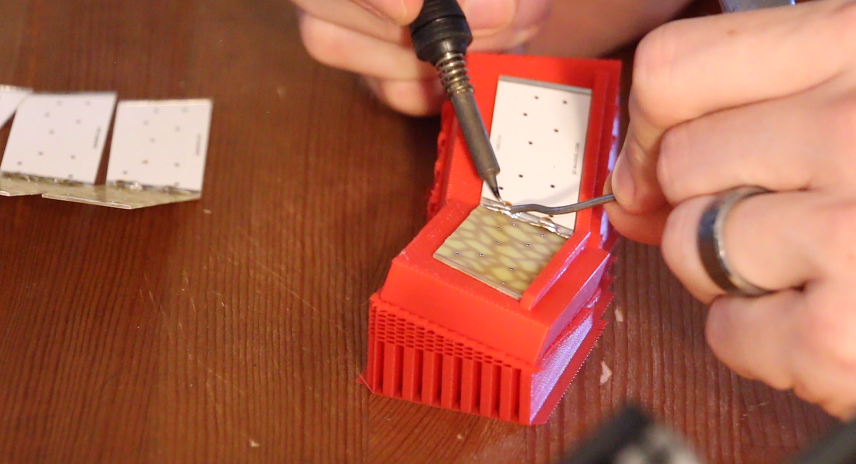
I’d already settled on a white silkscreen, to help reflecting light from within the shade outwards, but for the second design I opted to have no silkscreen, in the hopes of some of the light getting through the boards.
For the outside, after I mentioned this and the design limitations to my wife, she was kind enough to generate several different pattern options, making use of the copper and white silk screen combos. Having recently watched the excellent Technology Connection’s video on olden times touch lamps, I liked the idea of being able to touch the lampshade to turn it on. This would require a conductive surface.
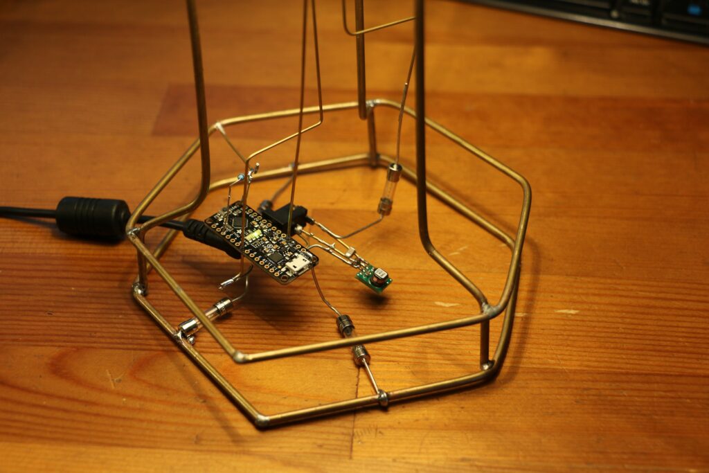
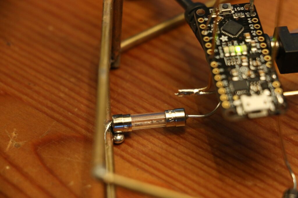
With that out of the way I turned to the electronics. I was going for quick and easy above all else, so settled on a small Arduino type controller. Doing some calculations, I realised I probably wanted a max total LED draw of around 10W. But the circuit sculpture nature of the design means cooling is difficult, so I heavily overspecced some LEDs and LED drivers.
I had a 19V power supply lying around, so worked from there. Although I later realized that the micro I’d chosen had a built in 16->5V regulator, so I could have taken advantage of that.
With the PCBs and electronics on order, I did some rough calcs for how much brass wire I’d need and went straight to McMaster Carr. Thereafter I spent as little time as possible designing some 3D printed jigs to make assembly easier. With mixed results.
Some quick prototyping when the electronics arrived had the lights and my ‘touch’ sensing working. Then it was just waiting for it all to arrive.
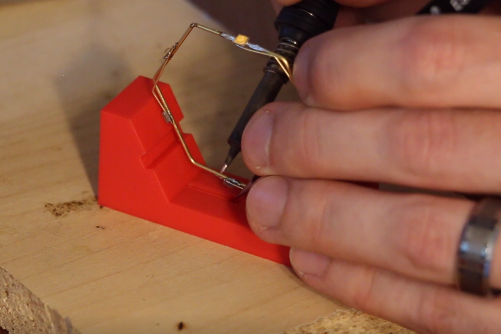
Assembly was grueling. For a number a reasons. I started off with the lamp shade rings. These went together fairly easily, and my printed jig made it super easy to solder this and ensure I got the right shape. Trying to attach all 8 levels of the shade together however was difficult. I was using 3mm brass wire, as I figured I’d need something sturdy. This is true, but it makes soldering to it difficult, as it takes a while to heat it up enough to get a decent structural bond. You may notice in my final photos that I got a bit of a slant to my shade as well. This is because I had no tools/jigs to help me keep the rods perpendicular to my lamp rings while soldering. TODO: Reduce use of 3mm brass rods.
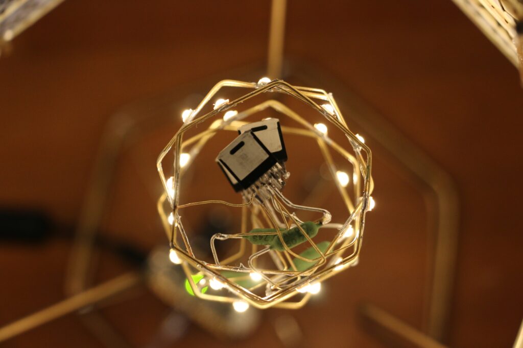
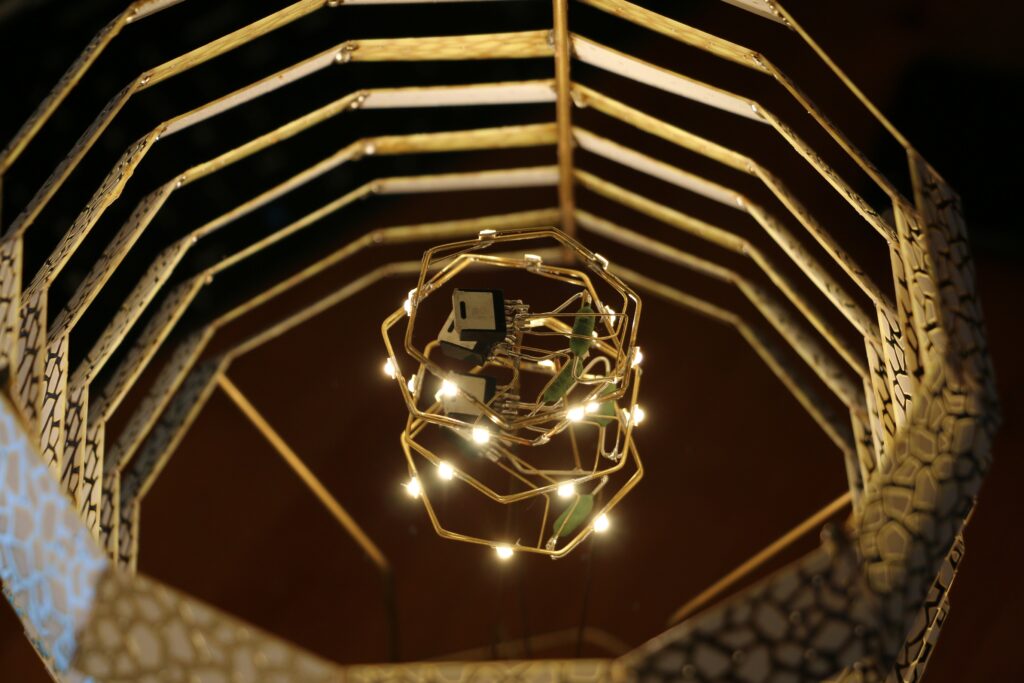
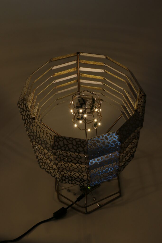
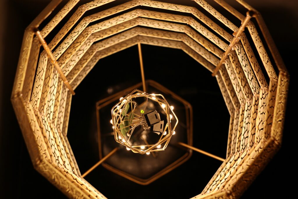
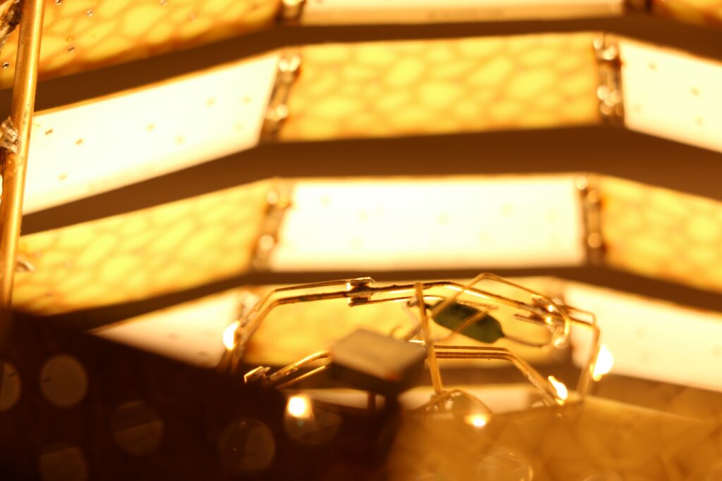
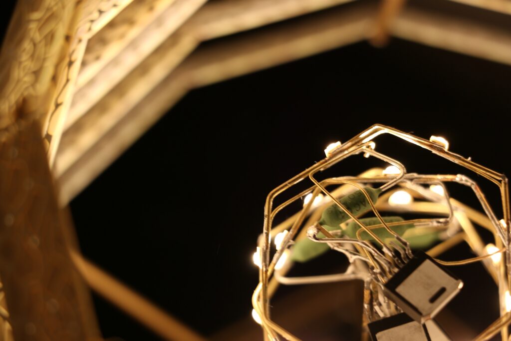
Next was the LED rings. I had to do 4 rings of 6 LEDs each. Hexagons, easy enough. I’d 3D printed a jig to help with this assembly. But I got a bit ahead of myself, not spending enough time to center the LEDs on each surface, which made my jig useless, and made connecting the LEDs to each other nightmarish. I had lots of cruddy solder joints and shorts which kept me busy for hours trying to debug. I ended up having to excise one of the rings once everything was all already assembled, completely rework it, and then place it back. Not fun. TODO: Make a better jig
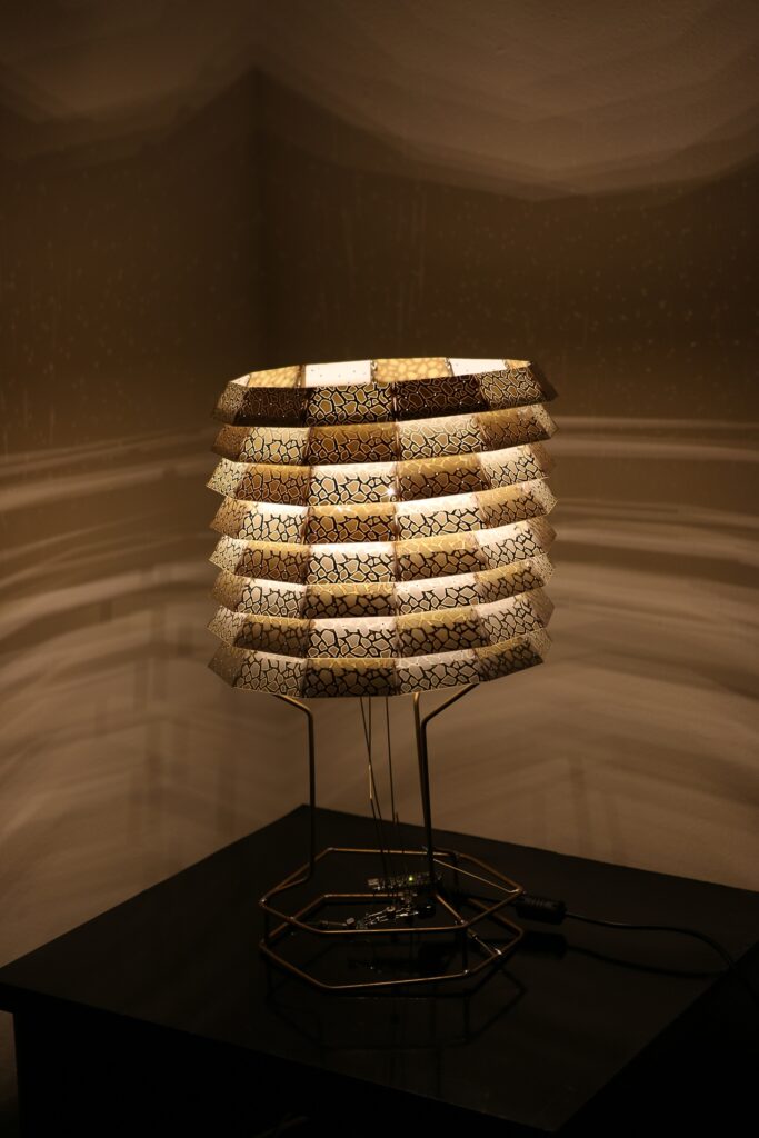
This is definitely not the typical interpretation of a circuit sculpture, and it’s a bit disappointing that the main visible electronics are the Arduino, and a regulator, both of which are soldered in a very non-aesthetically pleasing manner. The LED rings which actually look pretty impressive, if not neat, are hidden away behind the lampshade. That being said, the lampshade was supposed to be pretty. TODO: Plan component layout before soldering.
I had originally intended to have the contacts on the lamp shade be a type of touch sensor to turn the LEDs on and off. Unfortunately, although I put vias on the boards, and all of the boards are soldered together, I failed to connect the vias to the solder bridges. I probably could create additional solder bridges on the outer surface, but instead I opted to just make the frame of the lamp the touch sensor. TODO: Update lampshade PCBs to connect all surfaces.
Another problem is that the lights are suspended almost a foot above the electronics. All that is supporting them are three 1mm brass rods that absolutely mustn’t touch each other. Let’s just say that the lights tend to sway a bit when the lamp is bumped. Very visually appealing, and I haven’t had any shorts yet, but something sturdier is needed. TODO: Improve mounting of LEDs in shade.
Those are the main issues I encountered. It was a lot of fun. As impressive as I’ve always found the Circuit Sculptures in the past, trying to do one yourself definitely gives you a new appreciation for how much work goes into getting one that looks neat.

I took a number of videos as I was building up the different components. When I have some time I’ll try compile them.
UPDATE: I compiled them