
I have not avoided KiCad in any way, I just don’t use ECAD software much, and when I do, it’s largely for work where we have always used Altium. This year we got some work done by a contract firm. They mentioned they could use Altium, but it was their preference to use KiCad instead. We said that was fine. And all was good in the world.
Several months later and we want to produce something they’ve designed. They provide us all the KiCad files as well as manufacturing outputs, but for us to release this internally, we need to have it formatted in a specific way to match our QMS expected templates. This should be easy though, just apply a template and we’re good. KiCad has a Drawing Sheet Editor which lets you create worksheets, and apply them to your schematics and boards, that sounds like what we need.
And that is true. For schematics, I was able to create a template exactly matching our Altium one, and easily generate documents matching our existing documents. PCBAs on the other hand was a whole different ball game. This ‘issue’ is largely self-inflicted. Our release documentation requires a lot of things to be present in a 3-page PDF that aren’t necessarily that important. Mainly because it’s just duplicating data that is already contained in the Gerbers and other manufacturing output. This is just placed in a PDF that makes it easy for a human to get a quick overview of the design. It has its place.
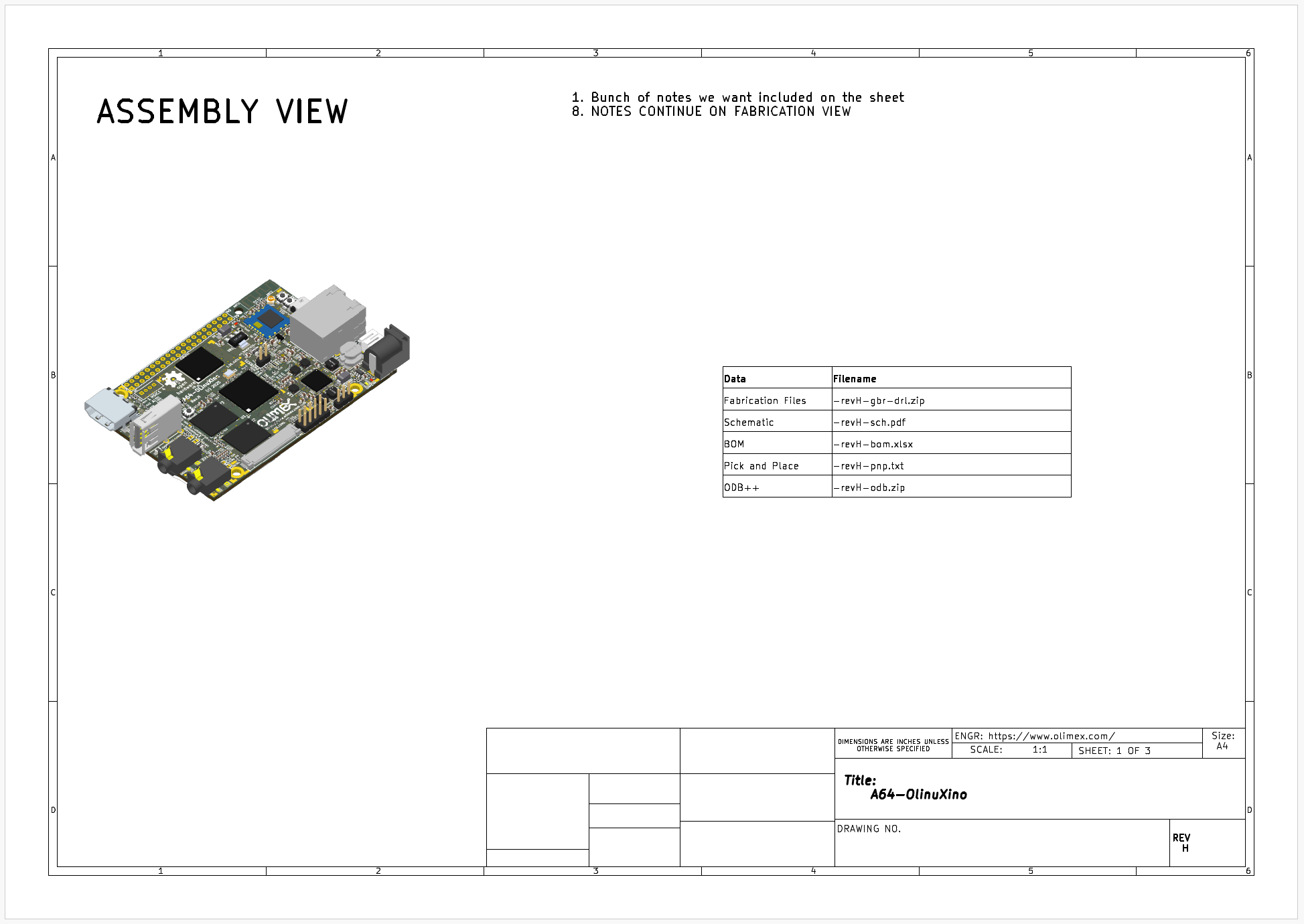
Included in this document are: a 3d-isometric view of the board; a PCB stack-up table; drill map; and a single page with all the layers shown. And Altium’s templates makes this trivial to generate for new designs. KiCad does not. And that’s not KiCad’s fault, it shouldn’t set out to just replicate everything Altium does. These aren’t things that are needed in an ECAD software, it’s just, we had it, and now we don’t.
So what can we do? We can apply a worksheet template to the PCB editor. But it can only really output each layer on a separate page. It’s a start. We can also have custom layers, and put whatever we want on those custom layers, which can be output to separate pages. What can’t we do? Mainly, the Drawing Sheet Editor (as far as I could tell) doesn’t let you template these additional layers’ contents. It can’t generate 3d images of the board, it can’t automatically populate a drill map or board stack-up table. KiCad does support most of these things, just not in an automated template kind of way, so if I wanted to to do this for every new design we release, it’s a lot of time consuming, error-prone work, to get the desired output.
What KiCad does have though is a newly revamped API, as well as several CLI options. And what can we do with these? Well, we can get a long way to matching our Altium implementation.
We can take 3 new layers, and pretend each of them is the desired output page we want. We can use the CLI to do things like generate drill maps and 3D views of the board. We can apply template sheets to the project, and we can generate the final files. We can then use the API to add the elements to our 3 layers; get information from the board and automatically generate table outputs. And then we can piece this together with a PDF editor library. Do we get exactly the same output as with Altium? No, but we get pretty close, and it has everything we need.
You can see a semi-stripped down version of this on GitHub.